

Multisegmented Nanowires: a Step towards the Control of the Domain Wall Configuration
- PMID: 28912534
- PMCID: PMC5599633
- DOI: 10.1038/s41598-017-11902-w
Multisegmented Nanowires: a Step towards the Control of the Domain Wall Configuration
Abstract
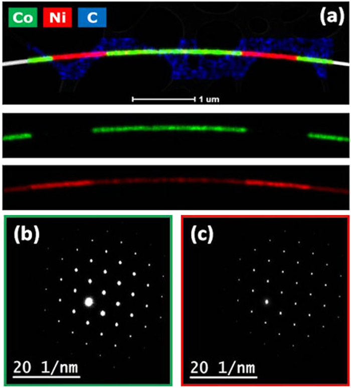
Cylindrical nanowires synthesized by controlled electrodeposition constitute excellent strategic candidates to engineer magnetic domain configurations. In this work, multisegmented CoNi/Ni nanowires are synthesized for tailoring a periodic magnetic structure determined by the balance between magnetocrystalline and magnetostatic energies. High-resolution Transmission Electron Microscopy confirms the segmented growth and the sharp transition between layers. Although both CoNi and Ni segments have similar fcc cubic crystal symmetry, their magnetic configuration is quite different as experimentally revealed by Magnetic Force Microscopy (MFM) imaging. While the Ni segments are single domain with axial magnetization direction, the CoNi segments present two main configurations: a single vortex state or a complex multivortex magnetic configuration, which is further interpreted with the help of micromagnetic simulations. This original outcome is ascribed to the tight competition between anisotropies. The almost monocrystalline fcc structure of the CoNi segments, as revealed by the electron diffraction patterns, which is atypical for its composition, contributes to balance the magnetocrystalline and shape anisotropies. The results of MFM measurements performed under in-plane magnetic field demonstrate that it is possible to switch from the multivortex configuration to a single vortex configuration with low magnetic fields.
Conflict of interest statement
The authors declare that they have no competing interests.
Figures


Similar articles
-
Distinguishing Local Demagnetization Contribution to the Magnetization Process in Multisegmented Nanowires.Nanomaterials (Basel). 2022 Jun 8;12(12):1968. doi: 10.3390/nano12121968. Nanomaterials (Basel). 2022. PMID: 35745306 Free PMC article.
-
Unveiling the Origin of Multidomain Structures in Compositionally Modulated Cylindrical Magnetic Nanowires.ACS Nano. 2020 Oct 27;14(10):12819-12827. doi: 10.1021/acsnano.0c03579. Epub 2020 Oct 1. ACS Nano. 2020. PMID: 32970409
-
Exotic Transverse-Vortex Magnetic Configurations in CoNi Nanowires.ACS Nano. 2020 Feb 25;14(2):1399-1405. doi: 10.1021/acsnano.9b07448. Epub 2019 Dec 13. ACS Nano. 2020. PMID: 31825584
-
A soft/hard magnetic nanostructure based on multisegmented CoNi nanowires.Phys Chem Chem Phys. 2015 Feb 21;17(7):5033-8. doi: 10.1039/c4cp05665e. Phys Chem Chem Phys. 2015. PMID: 25597517
-
Magnetic Configurations in Modulated Cylindrical Nanowires.Nanomaterials (Basel). 2021 Feb 28;11(3):600. doi: 10.3390/nano11030600. Nanomaterials (Basel). 2021. PMID: 33670880 Free PMC article. Review.
Cited by
-
Use of Two-Photon Lithography with a Negative Resist and Processing to Realise Cylindrical Magnetic Nanowires.Nanomaterials (Basel). 2020 Feb 28;10(3):429. doi: 10.3390/nano10030429. Nanomaterials (Basel). 2020. PMID: 32121262 Free PMC article.
-
Information storage in permalloy modulated magnetic nanowires.Sci Rep. 2021 Oct 21;11(1):20811. doi: 10.1038/s41598-021-00165-1. Sci Rep. 2021. PMID: 34675243 Free PMC article.
-
Multi-Segmented Nanowires: A High Tech Bright Future.Materials (Basel). 2019 Nov 26;12(23):3908. doi: 10.3390/ma12233908. Materials (Basel). 2019. PMID: 31779229 Free PMC article. Review.
-
Distinguishing Local Demagnetization Contribution to the Magnetization Process in Multisegmented Nanowires.Nanomaterials (Basel). 2022 Jun 8;12(12):1968. doi: 10.3390/nano12121968. Nanomaterials (Basel). 2022. PMID: 35745306 Free PMC article.
-
Modeling magnetic-field-induced domain wall propagation in modulated-diameter cylindrical nanowires.Sci Rep. 2019 Mar 26;9(1):5130. doi: 10.1038/s41598-019-40794-1. Sci Rep. 2019. PMID: 30914661 Free PMC article.
References
Publication types
LinkOut - more resources
Full Text Sources
Other Literature Sources
