

Hole-Transporting Materials for Printable Perovskite Solar Cells
- PMID: 28914823
- PMCID: PMC5615741
- DOI: 10.3390/ma10091087
Hole-Transporting Materials for Printable Perovskite Solar Cells
Abstract
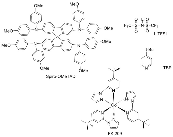
Perovskite solar cells (PSCs) represent undoubtedly the most significant breakthrough in photovoltaic technology since the 1970s, with an increase in their power conversion efficiency from less than 5% to over 22% in just a few years. Hole-transporting materials (HTMs) are an essential building block of PSC architectures. Currently, 2,2',7,7'-tetrakis-(N,N'-di-p-methoxyphenylamine)-9,9'-spirobifluorene), better known as spiro-OMeTAD, is the most widely-used HTM to obtain high-efficiency devices. However, it is a tremendously expensive material with mediocre hole carrier mobility. To ensure wide-scale application of PSC-based technologies, alternative HTMs are being proposed. Solution-processable HTMs are crucial to develop inexpensive, high-throughput and printable large-area PSCs. In this review, we present the most recent advances in the design and development of different types of HTMs, with a particular focus on mesoscopic PSCs. Finally, we outline possible future research directions for further optimization of the HTMs to achieve low-cost, stable and large-area PSCs.
Keywords: hole-transporting material; hybrid; inorganic; perovskite solar cells; polymer; printable; small-molecule.
Conflict of interest statement
The authors declare no conflict of interest.
Figures


Similar articles
-
Emerging of Inorganic Hole Transporting Materials For Perovskite Solar Cells.Chem Rec. 2017 Jul;17(7):681-699. doi: 10.1002/tcr.201600117. Epub 2017 Jan 4. Chem Rec. 2017. PMID: 28052541 Review.
-
Intensive Exposure of Functional Rings of a Polymeric Hole-Transporting Material Enables Efficient Perovskite Solar Cells.Adv Mater. 2018 Sep;30(39):e1804028. doi: 10.1002/adma.201804028. Epub 2018 Aug 21. Adv Mater. 2018. PMID: 30133039
-
Tetraphenylbutadiene-Based Symmetric 3D Hole-Transporting Materials for Perovskite Solar Cells: A Trial Trade-off between Charge Mobility and Film Morphology.ACS Appl Mater Interfaces. 2020 May 6;12(18):21088-21099. doi: 10.1021/acsami.0c02751. Epub 2020 Apr 21. ACS Appl Mater Interfaces. 2020. PMID: 32252526
-
Solution-Processed Cu(In, Ga)(S, Se)2 Nanocrystal as Inorganic Hole-Transporting Material for Efficient and Stable Perovskite Solar Cells.Nanoscale Res Lett. 2017 Dec;12(1):159. doi: 10.1186/s11671-017-1933-z. Epub 2017 Feb 28. Nanoscale Res Lett. 2017. PMID: 28249374 Free PMC article.
-
Perovskite Solar Cells: Influence of Hole Transporting Materials on Power Conversion Efficiency.ChemSusChem. 2016 Jan 8;9(1):10-27. doi: 10.1002/cssc.201501228. Epub 2015 Dec 21. ChemSusChem. 2016. PMID: 26692567 Review.
Cited by
-
Effect of thiophene rings rigidity on dye-sensitized solar cell performance. Dithienothiophene versus terthiophene as donor moiety.Heliyon. 2023 Oct 17;9(10):e21039. doi: 10.1016/j.heliyon.2023.e21039. eCollection 2023 Oct. Heliyon. 2023. PMID: 37886744 Free PMC article.
-
Dopant-Free π-Conjugated Hole Transport Materials for Highly Stable and Efficient Perovskite Solar Cells.Front Chem. 2021 Mar 18;9:664504. doi: 10.3389/fchem.2021.664504. eCollection 2021. Front Chem. 2021. PMID: 33816442 Free PMC article. Review.
-
Progress on the Synthesis and Application of CuSCN Inorganic Hole Transport Material in Perovskite Solar Cells.Materials (Basel). 2018 Dec 19;11(12):2592. doi: 10.3390/ma11122592. Materials (Basel). 2018. PMID: 30572658 Free PMC article. Review.
-
Optimizing Lignosulfonic Acid-Grafted Polyaniline as a Hole-Transport Layer for Inverted CH3NH3PbI3 Perovskite Solar Cells.ACS Omega. 2020 Jan 21;5(4):1887-1901. doi: 10.1021/acsomega.9b03451. eCollection 2020 Feb 4. ACS Omega. 2020. PMID: 32039325 Free PMC article.
-
N-Substituted Phenothiazines as Environmentally Friendly Hole-Transporting Materials for Low-Cost and Highly Stable Halide Perovskite Solar Cells.ACS Omega. 2020 Sep 1;5(36):23334-23342. doi: 10.1021/acsomega.0c03184. eCollection 2020 Sep 15. ACS Omega. 2020. PMID: 32954184 Free PMC article.
References
-
- BP Statistical Review of World Energy 2017. [(accessed on 3 August 2017)]; Available online: https://www.bp.com/content/dam/bp/en/corporate/pdf/energy-economics/stat....
-
- Golušin M., Dodić S., Popov S. Sustainable Energy Management. Academmic Press; Cambridge, MA, USA: 2013.
-
- Yu Z., Sun L. Recent Progress on Hole-Transporting Materials for Emerging Organometal Halide Perovskite Solar Cells. Adv. Energy Mater. 2015;5 doi: 10.1002/aenm.201500213. - DOI
Publication types
LinkOut - more resources
Full Text Sources
Other Literature Sources
