. 2017 Sep 19;7(1):11860.
doi: 10.1038/s41598-017-12107-x.

Aligning cellulose nanofibril dispersions for tougher fibers

Affiliations

Aligning cellulose nanofibril dispersions for tougher fibers

Pezhman Mohammadi et al. Sci Rep. .

Abstract

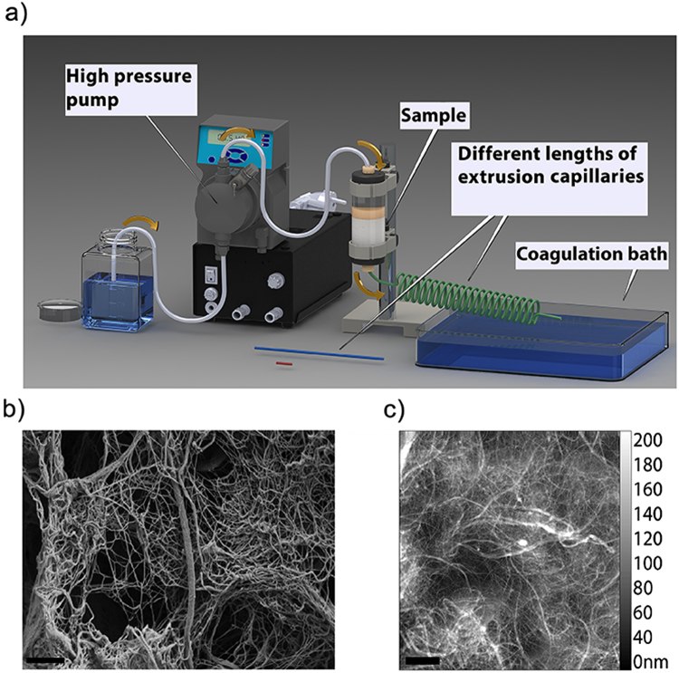
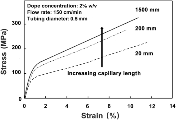
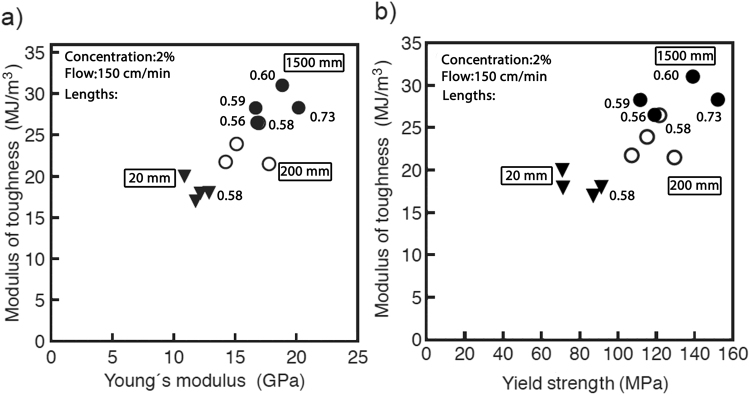
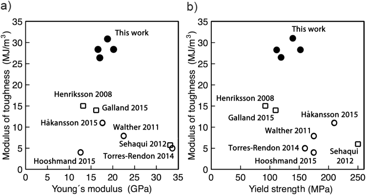
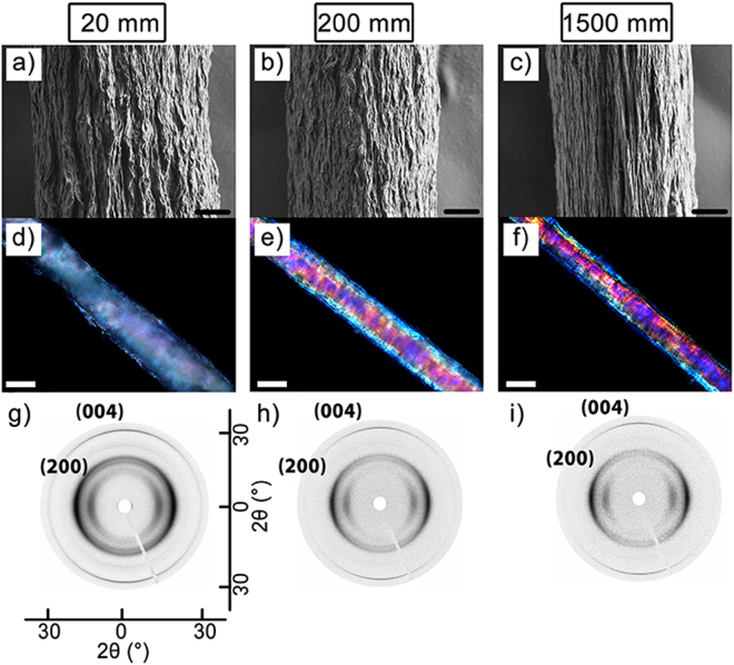
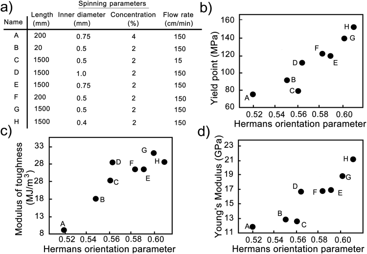
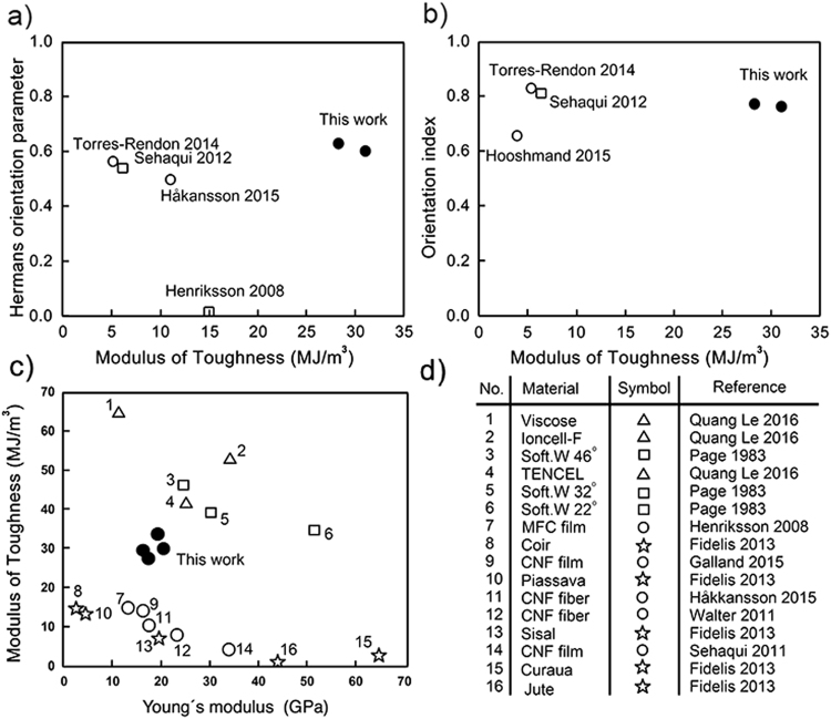
Nanocomposite materials made from cellulose show a great potential as future high-performance and sustainable materials. We show how high aspect ratio cellulose nanofibrils can be efficiently aligned in extrusion to fibers, leading to increased modulus of toughness (area under the stress-strain curve), Young's modulus, and yield strength by increasing the extrusion capillary length, decreasing its diameter, and increasing the flow rate. The materials showed significant property combinations, manifesting as high modulus of toughness (~28-31 MJ/m3) vs. high stiffness (~19-20 GPa), and vs. high yield strength (~130-150 MPa). Wide angle X-ray scattering confirmed that the enhanced mechanical properties directly correlated with increased alignment. The achieved moduli of toughness are approximately double or more when compared to values reported in the literature for corresponding strength and stiffness. Our results highlight a possibly general pathway that can be integrated to gel-spinning process, suggesting the hypothesis that that high stiffness, strength and toughness can be achieved simultaneously, if the alignment is induced while the CNF are in the free-flowing state during the extrusion step by shear at relatively low concentration and in pure water, after which they can be coagulated.


Conflict of interest statement

The authors declare that they have no competing interests.

Figures

Figure 1
Figure 1
The scheme of the spinning device and SEM and AFM images of the starting CNF. (a) The capillary length, the diameter, and the flow rate were modified, (b) SEM high magnification image of cellulose nanofibrils (CNF), (c) tapping mode AFM. The morphology and size distribution of the CNF were characterized by AFM and show fibrils with diameters in the range of 5 to 500 nm and lengths up to several micrometers since the ends of fibrils were not recognizable in the AFM topography images. Scale bars are 1 μm in both images.
Figure 2
Figure 2
Representative stress-strain curves of fibers spun using different capillary lengths. Capillary lengths: 1500 (solid), 200 (dot-dash), and 20 mm (dash). Other fiber spinning parameters were kept constant: the capillary inner diameter was 0.5 mm, CNF concentration was 2% w/v, and the flow rate was 150 cm/min.
Figure 3
Figure 3
The modulus of toughness vs. Young’s modulus (a) and yield strength (b) of the CNF fibers. Fibers spun by extruding the CNF dispersion through longer capillaries exhibit higher mechanical properties. Capillary lengths were 20 mm (filled inverted triangles), 200 mm 5 (empty circles), and 1500 mm (filled circles). The modulus of toughness was calculated from the area under the stress-strain curve. Plotting the modulus of toughness vs. either Young’s modulus (a), or yield strength (b) revealed a nearly linear positive correlation. Values next to selected data points denote the Hermans orientation parameters obtained for the corresponding fibers with WAXS (see below).
Figure 4
Figure 4
Modulus of toughness vs. Young’s modulus (a) and yield strength (b) for CNF fibers produced in this work (filled circles) in comparison to those reported in existing literature (empty symbols). In this work (filled circles) a modulus of toughness is observed at least twice as high as compared to films (empty squares) and fibers (empty circles) reported in the literature,,–,,. The four data points shown from this work are from fibers produced using 2% w/v CNF concentration, flow rate 150 cm/min and 1500 mm capillary but varying the inner diameter (0.4, 0.5, 0.75 and 1 mm).
Figure 5
Figure 5
Effect of the length of extrusion capillary on the alignment. The left, middle and right columns show data for fibers made with capillaries of 20, 200 and 1500 mm length respectively. SEM micrographs (a,b,c) represent the surface topology of the fibers showing and increasing smoothness/orientation of surface structures with capillary length. Optical birefringence of same fibers illustrating pronounced changes in the birefringence (d,e,f). Polarized optical microscopy images of corresponding CNF fibers showing increased birefringence for samples made with longer capillaries. WAXS diffractograms (g,h,i) of single fibers indicating increasing alignment with increasing capillary length. In all cases the capillary had an inner diameter of 0.5 mm, the CNF concentration was 2 % w/v, and the linear flow rate was 150 cm/min. Scale bars are 10 μm in (a,b, and c), and 50 μm in (d,e, and f).
Figure 6
Figure 6
A comprehensive correlation between CNF alignment and mechanical properties. (a) List of samples with one-letter codes used to identify samples in the plots. Hermans orientation parameter for (004) reflection correlated to (b) yield strength, (c) stiffness and (d) modulus of toughness for the fibers spun with different lengths and inner diameters of extrusion capillaries, and at high and low flow rates, and with different concentrations of CNF dispersion. Numeric values are listed in in Supplementary Table 4. Corresponding plots for ultimate strain, ultimate tensile strength and slope of the stress-strain curve after the yield point are in Supplementary Fig. S9.
Figure 7
Figure 7
Orientation parameters vs. modulus of toughness. (a) Hermans orientation parameter and (b) orientation index plotted against the modulus of toughness. Degrees of orientation reached in this work (filled circles) were very similar to those of actively oriented fibers (empty circles) and films (empty squares) reported in the literature,–. Note that the films by Sehaqui et al. were oriented by drawing before drying whereas those by Henriksson et al. were not drawn. Additionally, the shown values for orientation parameters of films are for the in-plane orientation. Both Hermans orientation and orientation index are plotted because both the values are not available for all relevant works. (c) and (d) Modulus of toughness vs. Young’s modulus for natural cellulosic fibers (empty squares and empty stars),, regenerated cellulose based fibers (empty triangles), reported CNF based fibers from literature,,–,, (empty circles) and this work (filled circles). Materials are numbered in order of decreasing toughness value.

References

    1. Wegst UGK, Bai H, Saiz E, Tomsia AP, Ritchie RO. Bioinspired structural materials. Nat. Mater. 2015;14:23–36. doi: 10.1038/nmat4089. - DOI - PubMed
    1. Fratzl P. Cellulose and collagen: from fibres to tissues. Curr. Opin. Colloid Interface Sci. 2003;8:32–39. doi: 10.1016/S1359-0294(03)00011-6. - DOI
    1. Fratzl, P., Kolednik, O., Fischer, F. D. & Dean, M. N. The mechanics of tessellations–bioinspired strategies for fracture resistance. Chem. Soc. Rev. (2016). - PubMed
    1. Fratzl, P. in Learning from nature how to design new implantable biomaterialsis: From Biomineralization fundamentals to biomimetic materials and processing routes 15–34 (Springer, 2004).
    1. Aizenberg J, et al. Skeleton of Euplectella sp.: structural hierarchy from the nanoscale to the macroscale. Science (80−.). 2005;309:275–278. doi: 10.1126/science.1112255. - DOI - PubMed

Publication types