

Corneal Biomechanics in Ectatic Diseases: Refractive Surgery Implications
- PMID: 28932334
- PMCID: PMC5585467
- DOI: 10.2174/1874364101711010176
Corneal Biomechanics in Ectatic Diseases: Refractive Surgery Implications
Abstract
Background: Ectasia development occurs due to a chronic corneal biomechanical decompensation or weakness, resulting in stromal thinning and corneal protrusion. This leads to corneal steepening, increase in astigmatism, and irregularity. In corneal refractive surgery, the detection of mild forms of ectasia pre-operatively is essential to avoid post-operative progressive ectasia, which also depends on the impact of the procedure on the cornea.
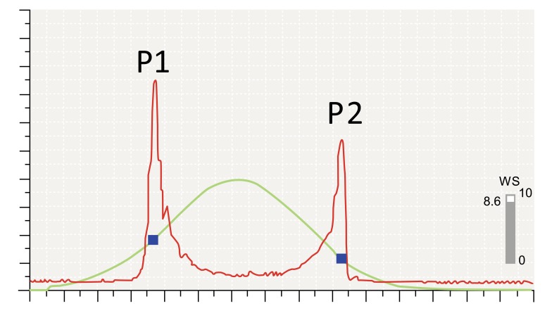
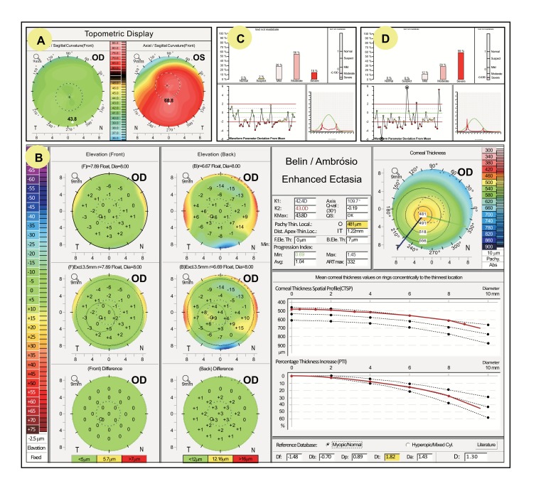
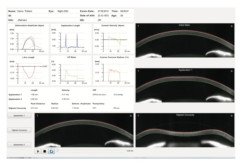
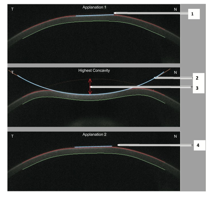
Method: The advent of 3D tomography is proven as a significant advancement to further characterize corneal shape beyond front surface topography, which is still relevant. While screening tests for ectasia had been limited to corneal shape (geometry) assessment, clinical biomechanical assessment has been possible since the introduction of the Ocular Response Analyzer (Reichert Ophthalmic Instruments, Buffalo, USA) in 2005 and the Corvis ST (Oculus Optikgeräte GmbH, Wetzlar, Germany) in 2010. Direct clinical biomechanical evaluation is recognized as paramount, especially in detection of mild ectatic cases and characterization of the susceptibility for ectasia progression for any cornea.
Conclusions: The purpose of this review is to describe the current state of clinical evaluation of corneal biomechanics, focusing on the most recent advances of commercially available instruments and also on future developments, such as Brillouin microscopy.
Figures
Similar articles
-
The Role of Corneal Biomechanics for the Evaluation of Ectasia Patients.Int J Environ Res Public Health. 2020 Mar 23;17(6):2113. doi: 10.3390/ijerph17062113. Int J Environ Res Public Health. 2020. PMID: 32209975 Free PMC article.
-
Importance and use of corneal biomechanics and its diagnostic utility.Cir Cir. 2023;91(6):848-857. doi: 10.24875/CIRU.23000260. Cir Cir. 2023. PMID: 38096874 Review. English.
-
Biomechanics in Keratoconus Diagnosis.Curr Eye Res. 2023 Feb;48(2):130-136. doi: 10.1080/02713683.2022.2041042. Epub 2022 Mar 21. Curr Eye Res. 2023. PMID: 35184637
-
Long-term Evaluation of Corneal Biomechanical Properties After Corneal Cross-linking for Keratoconus: A 4-Year Longitudinal Study.J Refract Surg. 2018 Dec 1;34(12):849-856. doi: 10.3928/1081597X-20181012-02. J Refract Surg. 2018. PMID: 30540368
-
Biomechanical diagnostics of the cornea.Eye Vis (Lond). 2020 Feb 5;7:9. doi: 10.1186/s40662-020-0174-x. eCollection 2020. Eye Vis (Lond). 2020. PMID: 32042837 Free PMC article. Review.
Cited by
-
Determination of Corneal Biomechanical Behavior in-vivo for Healthy Eyes Using CorVis ST Tonometry: Stress-Strain Index.Front Bioeng Biotechnol. 2019 May 16;7:105. doi: 10.3389/fbioe.2019.00105. eCollection 2019. Front Bioeng Biotechnol. 2019. PMID: 31157217 Free PMC article.
-
Evaluation of corneal biomechanical properties using the ocular response analyzer and the dynamic Scheimpflug-Analyzer Corvis ST in high pressure and normal pressure open-angle glaucoma patients.PLoS One. 2023 Jan 26;18(1):e0281017. doi: 10.1371/journal.pone.0281017. eCollection 2023. PLoS One. 2023. PMID: 36701409 Free PMC article.
-
The Role of Corneal Biomechanics for the Evaluation of Ectasia Patients.Int J Environ Res Public Health. 2020 Mar 23;17(6):2113. doi: 10.3390/ijerph17062113. Int J Environ Res Public Health. 2020. PMID: 32209975 Free PMC article.
-
Keratectasia severity staging and progression assessment based on the biomechanical E-staging.Eye Vis (Lond). 2024 Jul 1;11(1):24. doi: 10.1186/s40662-024-00392-3. Eye Vis (Lond). 2024. PMID: 38946004 Free PMC article. Review.
-
Estimation of scleral mechanical properties from air-puff optical coherence tomography.Biomed Opt Express. 2021 Sep 17;12(10):6341-6359. doi: 10.1364/BOE.437981. eCollection 2021 Oct 1. Biomed Opt Express. 2021. PMID: 34745741 Free PMC article.
References
-
- Binder P.S., Lindstrom R.L., Stulting R.D., Donnenfeld E., Wu H., McDonnell P., Rabinowitz Y. Keratoconus and corneal ectasia after LASIK. J. Refract. Surg. 2005;21(6):749–752. - PubMed
LinkOut - more resources
Full Text Sources
Other Literature Sources