

Calibration and error analysis of metal-oxide-semiconductor field-effect transistor dosimeters for computed tomography radiation dosimetry
- PMID: 28940306
- PMCID: PMC5734630
- DOI: 10.1002/mp.12592
Calibration and error analysis of metal-oxide-semiconductor field-effect transistor dosimeters for computed tomography radiation dosimetry
Abstract
Purpose: Metal-oxide-semiconductor field-effect transistors (MOSFETs) serve as a helpful tool for organ radiation dosimetry and their use has grown in computed tomography (CT). While different approaches have been used for MOSFET calibration, those using the commonly available 100 mm pencil ionization chamber have not incorporated measurements performed throughout its length, and moreover, no previous work has rigorously evaluated the multiple sources of error involved in MOSFET calibration. In this paper, we propose a new MOSFET calibration approach to translate MOSFET voltage measurements into absorbed dose from CT, based on serial measurements performed throughout the length of a 100-mm ionization chamber, and perform an analysis of the errors of MOSFET voltage measurements and four sources of error in calibration.
Methods: MOSFET calibration was performed at two sites, to determine single calibration factors for tube potentials of 80, 100, and 120 kVp, using a 100-mm-long pencil ion chamber and a cylindrical computed tomography dose index (CTDI) phantom of 32 cm diameter. The dose profile along the 100-mm ion chamber axis was sampled in 5 mm intervals by nine MOSFETs in the nine holes of the CTDI phantom. Variance of the absorbed dose was modeled as a sum of the MOSFET voltage measurement variance and the calibration factor variance, the latter being comprised of three main subcomponents: ionization chamber reading variance, MOSFET-to-MOSFET variation and a contribution related to the fact that the average calibration factor of a few MOSFETs was used as an estimate for the average value of all MOSFETs. MOSFET voltage measurement error was estimated based on sets of repeated measurements. The calibration factor overall voltage measurement error was calculated from the above analysis.
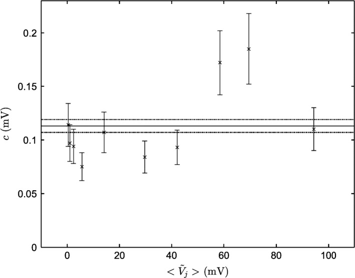
Results: Calibration factors determined were close to those reported in the literature and by the manufacturer (~3 mV/mGy), ranging from 2.87 to 3.13 mV/mGy. The error σV of a MOSFET voltage measurement was shown to be proportional to the square root of the voltage V: σV=cV where c = 0.11 mV. A main contributor to the error in the calibration factor was the ionization chamber reading error with 5% error. The usage of a single calibration factor for all MOSFETs introduced an additional error of about 5-7%, depending on the number of MOSFETs that were used to determine the single calibration factor. The expected overall error in a high-dose region (~30 mGy) was estimated to be about 8%, compared to 6% when an individual MOSFET calibration was performed. For a low-dose region (~3 mGy), these values were 13% and 12%.
Conclusions: A MOSFET calibration method was developed using a 100-mm pencil ion chamber and a CTDI phantom, accompanied by an absorbed dose error analysis reflecting multiple sources of measurement error. When using a single calibration factor, per tube potential, for different MOSFETs, only a small error was introduced into absorbed dose determinations, thus supporting the use of a single calibration factor for experiments involving many MOSFETs, such as those required to accurately estimate radiation effective dose.
Keywords: MOSFET; calibration; dosimetry; ion chamber; measurement error.
© 2017 American Association of Physicists in Medicine.
Conflict of interest statement
Dr. Einstein has received research grants to Columbia University for other research from GE Healthcare and Toshiba America Medical Systems. Dr. Prinsen, Dr. Wiegert, Dr. Gerland, Dr. Shefer, Dr. Morton, Dr. Yagil and Dr. Halliburton are employees of Royal Philips.
Figures


Similar articles
-
Establishing a standard calibration methodology for MOSFET detectors in computed tomography dosimetry.Med Phys. 2012 Jun;39(6):3031-40. doi: 10.1118/1.4712221. Med Phys. 2012. PMID: 22755688
-
High correlation between radiation dose estimates for 256-slice CT obtained by highly parallelized hybrid Monte Carlo computation and solid-state metal-oxide semiconductor field-effect transistor measurements in physical anthropomorphic phantoms.Med Phys. 2019 Nov;46(11):5216-5226. doi: 10.1002/mp.13780. Epub 2019 Sep 18. Med Phys. 2019. PMID: 31442300
-
MOSFET detectors in quality assurance of tomotherapy treatments.Radiother Oncol. 2008 Feb;86(2):242-50. doi: 10.1016/j.radonc.2007.10.025. Epub 2007 Nov 26. Radiother Oncol. 2008. PMID: 18037519
-
P-channel MOSFET as ionizing radiation detector.Appl Radiat Isot. 2023 Jun;196:110730. doi: 10.1016/j.apradiso.2023.110730. Epub 2023 Mar 1. Appl Radiat Isot. 2023. PMID: 36871494 Review.
-
A Review: Photonic Devices Used for Dosimetry in Medical Radiation.Sensors (Basel). 2019 May 14;19(10):2226. doi: 10.3390/s19102226. Sensors (Basel). 2019. PMID: 31091779 Free PMC article. Review.
Cited by
-
Application of low-dose CT to the creation of 3D-printed kidney and perinephric tissue models for laparoscopic nephrectomy.Cancer Med. 2021 May;10(9):3077-3084. doi: 10.1002/cam4.3851. Epub 2021 Apr 2. Cancer Med. 2021. PMID: 33797861 Free PMC article.
-
Dosimetric assessment of the exposure of radiotherapy patients due to cone-beam CT procedures.Radiat Environ Biophys. 2019 Mar;58(1):21-37. doi: 10.1007/s00411-018-0760-7. Epub 2018 Nov 3. Radiat Environ Biophys. 2019. PMID: 30392077
-
Cardiac-Specific Conversion Factors to Estimate Radiation Effective Dose From Dose-Length Product in Computed Tomography.JACC Cardiovasc Imaging. 2018 Jan;11(1):64-74. doi: 10.1016/j.jcmg.2017.06.006. Epub 2017 Aug 16. JACC Cardiovasc Imaging. 2018. PMID: 28823748 Free PMC article.
References
-
- Hurwitz LM, Yoshizumi TT, Goodman PC, Frush DP. Effective dose determination using an anthropomorphic phantom and metal oxide semiconductor field effect transistor technology for clinical adult body multidetector array computed tomography protocols. J Comput Assist Tomogr. 2007;31:544–549. - PubMed
-
- Peet DJ, Pryor MD. Evaluation of a MOSFET radiation sensor for the measurement of entrance surface dose in diagnostic radiology. Br J Radiol. 1999;72:562–568. - PubMed
-
- Ehringfeld C, Schmid S, Poljanc K, Kirisits C, Aiginger H, Georg D. Application of commercial MOSFET detectors for in vivo dosimetry in the therapeutic x‐ray range from 80 kV to 250 kV. Phys Med Biol. 2005;50:289–303. - PubMed
-
- Brady SL, Kaufman RA. Establishing a standard calibration methodology for MOSFET detectors in computed tomography dosimetry. Med Phys. 2012;39:3031–3040. - PubMed
-
- Syam Kumar SA, Sukumar P, Sriram P, Rajasekaran D, Aketi S, Vivekanandan N. A patient‐specific quality assurance study on absolute dose verification using ionization chambers of different volumes in RapidArc treatments. Med Dosim. 2012;37:436–441. - PubMed
MeSH terms
Substances
Grants and funding
LinkOut - more resources
Full Text Sources
Other Literature Sources
Medical
