Review
. 2017 Nov 7;28(23):3134-3155.
doi: 10.1091/mbc.E17-04-0228. Epub 2017 Sep 27.

Receptor-mediated cell mechanosensing

Affiliations
Review

Receptor-mediated cell mechanosensing

Yunfeng Chen et al. Mol Biol Cell. .

Abstract

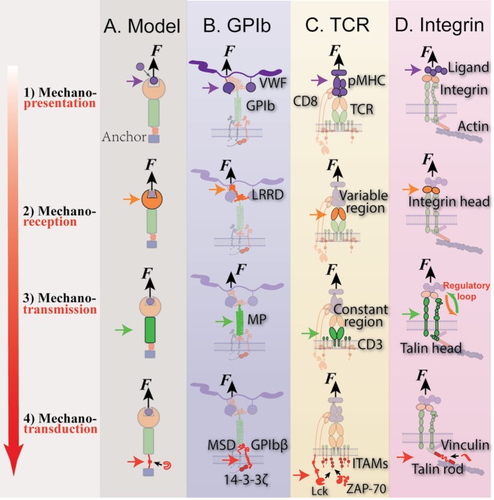
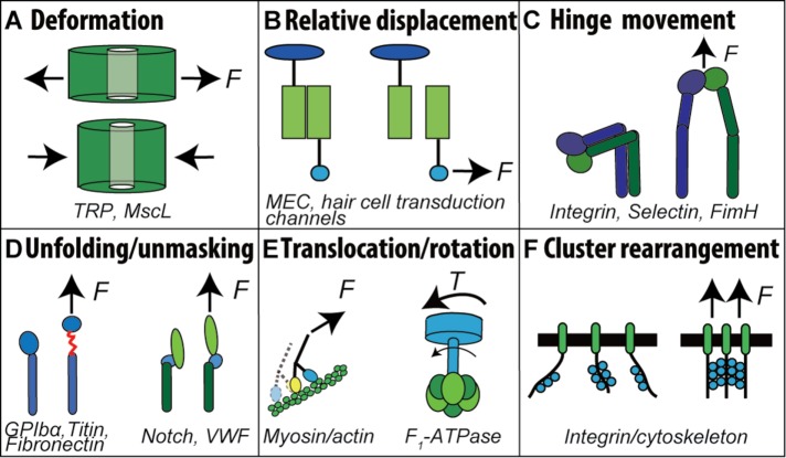
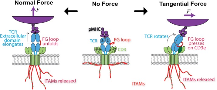
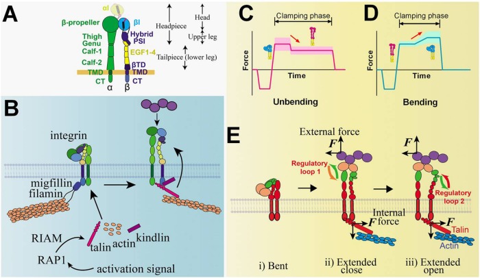
Mechanosensing describes the ability of a cell to sense mechanical cues of its microenvironment, including not only all components of force, stress, and strain but also substrate rigidity, topology, and adhesiveness. This ability is crucial for the cell to respond to the surrounding mechanical cues and adapt to the changing environment. Examples of responses and adaptation include (de)activation, proliferation/apoptosis, and (de)differentiation. Receptor-mediated cell mechanosensing is a multistep process that is initiated by binding of cell surface receptors to their ligands on the extracellular matrix or the surface of adjacent cells. Mechanical cues are presented by the ligand and received by the receptor at the binding interface; but their transmission over space and time and their conversion into biochemical signals may involve other domains and additional molecules. In this review, a four-step model is described for the receptor-mediated cell mechanosensing process. Platelet glycoprotein Ib, T-cell receptor, and integrins are used as examples to illustrate the key concepts and players in this process.


Figures

FIGURE 1:
FIGURE 1:
Model of mechanosensing with three exemplary systems (GPIb, TCR, and integrin), which is broken into four steps: 1) mechanopresentation; 2) mechanoreception; 3) mechanotransmission; and 4) mechanotransduction. Purple, orange, green, and red arrows indicate the location of each step carried out by a molecule or molecular assembly: the mechanopresenter, mechanoreceptor, mechanotransmitter, and mechanotransducer, respectively. Black arrows indicates external force, F. Steps of mechanosensing of a generic model (A) and three model systems, GPIb (B), TCR (C), and integrin (D), were depicted in correspondence to the proposed model. Due to the existence of multiple mechanosensing mechanisms in integrins, the talin unfolding mechanism is selected as representative in D.
FIGURE 2:
FIGURE 2:
Mechanisms of protein mechanosensitivity. Mechanosensitive proteins contain a motif or motifs that can change structure in response to mechanical forces, giving rise to (A) deformation, (B) relative displacement, (C) hinge movement, (D) unfolding and unmasking, (E) translocation and rotation, and (F) cluster rearrangement.
FIGURE 3:
FIGURE 3:
Single-molecule force probe techniques (A–E) and microscopic probes for cell tractions and intracellular forces (F–L) techniques. (A) A generic force probe that applies forces (F) to the receptor–ligand bond spanning a surface and a force transducer. (B) Atomic force microscopy (AFM): force is applied to individual molecules tethered between a functionalized cantilever and a surface. (C) Optical tweezers (OT): a protein-coated bead is held by a laser beam. (D) Magnetic tweezers (MT): permanent/electrical magnets are used to manipulate a protein-coated magnetic bead. (E) Biomembrane force probe (BFP): the protein-coated bead is attached to the apex of a micropipette-aspirated red blood cell (RBC). (B–E) Force is determined respectively by cantilever deflection (B), bead displacement (C), gradient of the magnetic field (D), and RBC deformation (E). (F) Extracellular and intracellular tension sensors allow microscopic observation of endogenous forces experienced by different proteins. (G) Nanopost: the deflections of the polydimethylsiloxane posts reflect the lateral components of tractions exerted by adhered cells. (H) Tension gauge tethers (TGTs): DNA strands with defined tension tolerances are repurposed to test the tension required to activate cell adhesion. (I) Molecular tension-based fluorescence microscopic probe. The fluorophore and quencher are coupled to report the force-induced unfolding of the DNA hairpin, thereby unquenching the fluorescence to report the molecular forces. (J) Gold nanoparticle-based ratiometric tension probes on supported lipid bilayer monitor hairpin opening due to force while controlling for clustering of mobile ligands using a secondary fluorescent readout. (K) Elastomer force probes report drop in FRET signal due to the elongation of the nanospring domain upon force application. (L) Intracellular force probes genetically inserted into domains of intracellular proteins allow force measurement of key domains involved in mechanotransduction inside the cell.
FIGURE 4:
FIGURE 4:
Identification and characterization of GPIb mechanosensing mechanism. (A, B) Schematics of GPIb on the platelet membrane, highlighting the folded (−) and unfolded (+) LRRD and MSD. Ligand binding domain for VWF-A1 and other regions are indicated. (C–F) Illustrative BFP force traces showing zoom-in views of unfolding signatures in both ramping and clamping phases. (G, H) Illustrative analysis of GPIb-mediated single-platelet Ca2+ flux. Top, pseudo-colored images of intracellular Ca2+ in platelets in time sequences. Bottom, time courses of normalized intracellular Ca2+ intensity of the α (G) and β (H) types.
FIGURE 5:
FIGURE 5:
Models of how force may trigger TCR signaling. Middle, schematic of the ligated, unloaded, and untriggered TCR. Soluble pMHC binds to the TCR V domains, while the CTs of the TCR-associated CD3 chains remain buried in the lower leaflet of the cell membrane, preventing ITAM phosphorylation. Left, a force normal to the cell membrane pulls on the TCR, extending the length of the complex by ∼10 nm. While the structural region responsible for such conformational change has not been identified, here the FG loop connecting the Cβ and Vβ domains is assumed to unfold to result in an extended conformer and in catch-bond formation. Force propagated across the TCR-CD3 connection is assumed to release the CD3 CTs for phosphorylation of the ITAMs. Right, when a force tangential to the cell surface is applied to the ligand binding site of the TCR that also experiences a lateral reaction force from its membrane anchor, a torque is generated to rotate the complex, which is assumed to allow the FG loop to press down on the CD3ε ectodomain to expose the cytoplasmic ITAMs in a piston-like manner.
FIGURE 6:
FIGURE 6:
Integrin structure and signaling models and illustrative BFP signals that detect integrin bending and unbending. (A) Integrin structure. Domains of the integrin and the ranges of integrin head, upper leg, headpiece, and tailpiece (or lower leg) are annotated. αI domain that exists only in αI-bearing integrins is distinguished by a lighter color and dashed lines. (B) A model of integrin inside-out signaling mediated by RAP1 and RIAM. (C, D) Illustrative BFP force vs. time traces depicting respective integrin unbending (C) and bending (D) conformational change events, denoted by red arrows. The conformations of the integrin are inserted accordingly, with red and blue indicating the extended and bent conformers of the ectodomain, respectively. Widths of the shaded regions reflect the thermal fluctuation amplitude of each trace in the clamping phase. (E) Postulated model of integrin-mediated mechanosensing without prior talin engagement. External force pulls on the i) bent integrin headpiece and allosterically induces ii) ectodomain extension, iii) hybrid domain swing-out, and αβ-subunit separation below the headpiece due to an endogenous lateral force pulling on the βCT. The αβ separation at the CT presumably recruits intracellular molecules and initiates downstream signaling. The ligand, integrin domains, and talin are colored based on their respective roles in the four-step mechanosensing model (cf. Figure 1). Proposed regulatory loops 1 (between mechanoreception and mechanotransmission) and 2 (between mechanotransmission and mechanotransduction) are denoted.

Similar articles

Cited by

References

    1. Adams JJ, Narayanan S, Liu B, Birnbaum ME, Kruse AC, Bowerman NA, Chen W, Levin AM, Connolly JM, Zhu C, et al. T cell receptor signaling is limited by docking geometry to peptide-major histocompatibility complex. Immunity. 2011;35:681–693. - PMC - PubMed
    1. Andresen Eguiluz RC, Kaylan KB, Underhill GH, Leckband DE. Substrate stiffness and VE-cadherin mechano-transduction coordinate to regulate endothelial monolayer integrity. Biomaterials. 2017;140:45–57. - PMC - PubMed
    1. Aponte-Santamaria C, Huck V, Posch S, Bronowska AK, Grassle S, Brehm MA, Obser T, Schneppenheim R, Hinterdorfer P, Schneider SW, et al. Force-sensitive autoinhibition of the von Willebrand factor is mediated by interdomain interactions. Biophys J. 2015;108:2312–2321. - PMC - PubMed
    1. Arnaout MA, Mahalingam B, Xiong JP. Integrin structure, allostery, and bidirectional signaling. Annu Rev Cell Dev Biol. 2005;21:381–410. - PubMed
    1. Auton M, Sowa KE, Behymer M, Cruz MA. N-terminal flanking region of A1 domain in von Willebrand factor stabilizes structure of A1A2A3 complex and modulates platelet activation under shear stress. J Biol Chem. 2012;287:14579–14585. - PMC - PubMed

LinkOut - more resources