Evaluation of Common RF Coil Setups for MR Imaging at Ultrahigh Magnetic Field: A Numerical Study
- PMID: 28966929
- PMCID: PMC5619668
- DOI: 10.1145/2093698.2093768
Evaluation of Common RF Coil Setups for MR Imaging at Ultrahigh Magnetic Field: A Numerical Study
Abstract
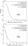
This study is an evaluation of the ratio of electric field to magnetic field (E/B1), specific absorption rate (SAR) and signal-to-noise ratio (SNR) generated by three different RF transceiver coil setups: surface coil, surface coil with shielding, and microstrip using a finite discrete time domain (FDTD) simulation in the presence of a head phantom. One of our main focuses in this study is to better understand coil designs that would improve patient safety at high fields by studying a coil type that may potentially minimize SAR while examining potential changes in SNR. In the presence of a human head load, the microstrip's E/B1 ratio was on average smallest while its SAR was also on average smallest of the three setups, suggesting the microstrip may be a better RF coil choice for MRI concerning patient safety and parallel excitation applications than the other two coils. In addition, the study suggests that the microstrip also has a higher SNR compared with the other two coils demonstrating the possibility that the microstrip could lead to higher quality MRI images.
Keywords: High field; RF coil; electromagnetic calculation; microstrip; numerical modeling; signal-to-noise ratio (SNR); specific absorption rate (SAR).
Figures


Similar articles
-
B1 field, SAR, and SNR comparisons for birdcage, TEM, and microstrip coils at 7T.J Magn Reson Imaging. 2006 Aug;24(2):439-43. doi: 10.1002/jmri.20635. J Magn Reson Imaging. 2006. PMID: 16786582
-
Microstrip RF surface coil design for extremely high-field MRI and spectroscopy.Magn Reson Med. 2001 Sep;46(3):443-50. doi: 10.1002/mrm.1212. Magn Reson Med. 2001. PMID: 11550234
-
RF Head Coil Design with Improved RF Magnetic Near-Fields Uniformity for Magnetic Resonance Imaging (MRI) Systems.IEEE Trans Microw Theory Tech. 2014 Aug;62(8):1784-1789. doi: 10.1109/tmtt.2014.2331621. IEEE Trans Microw Theory Tech. 2014. PMID: 25892746 Free PMC article.
-
Machine Learning for the Design and the Simulation of Radiofrequency Magnetic Resonance Coils: Literature Review, Challenges, and Perspectives.Sensors (Basel). 2024 Mar 19;24(6):1954. doi: 10.3390/s24061954. Sensors (Basel). 2024. PMID: 38544216 Free PMC article. Review.
-
Use of the Perturbing Sphere Method for the Estimation of Radiofrequency Coils' Efficiency in Magnetic Resonance Applications: Experience from an Electromagnetic Laboratory.Sensors (Basel). 2024 Sep 2;24(17):5705. doi: 10.3390/s24175705. Sensors (Basel). 2024. PMID: 39275616 Free PMC article. Review.
Cited by
-
Human fall direction recognition in the indoor and outdoor environment using multi self-attention RBnet deep architectures and tree seed optimization.Sci Rep. 2025 Aug 4;15(1):28475. doi: 10.1038/s41598-025-11031-9. Sci Rep. 2025. PMID: 40760069 Free PMC article.
-
From complex B(1) mapping to local SAR estimation for human brain MR imaging using multi-channel transceiver coil at 7T.IEEE Trans Med Imaging. 2013 Jun;32(6):1058-67. doi: 10.1109/TMI.2013.2251653. Epub 2013 Mar 11. IEEE Trans Med Imaging. 2013. PMID: 23508259 Free PMC article.
-
Image homogenization using pre-emphasis method for high field MRI.Quant Imaging Med Surg. 2013 Aug;3(4):217-23. doi: 10.3978/j.issn.2223-4292.2013.07.01. Quant Imaging Med Surg. 2013. PMID: 24040618 Free PMC article.
-
Mind the gap: State-of-the-art technologies and applications for EEG-based brain-computer interfaces.APL Bioeng. 2021 Jul 20;5(3):031507. doi: 10.1063/5.0047237. eCollection 2021 Sep. APL Bioeng. 2021. PMID: 34327294 Free PMC article. Review.
References
-
- Abragam A. The Principles of Nuclear Magnetism. Oxford University Press; London, England: 1961.
-
- Lauterbur PC. Image formation by induced local interactions: Examples employing nuclear magnetic resonance. Nature. 1973;242:190–191. - PubMed
-
- Mansfield P, Morris PG. NMR Imaging in Biomedicine. Academic Press Inc; Orlando, Florida: 1982.
-
- Nishimura D. Principles of Magnetic Resonance Imaging. Lulu; Stanford, CA: 2010.
-
- Wright SM, Enderle J, Blanchard S, Bronzino J. NMR-MRI, Chapter 16 in Introduction to Biomedical Engineering. Academic Press; New York: 1999.
Grants and funding
LinkOut - more resources
Full Text Sources
Other Literature Sources
Miscellaneous
