

Review
doi: 10.3390/s17102284.
Gyroscope Technology and Applications: A Review in the Industrial Perspective
Affiliations
- PMID: 28991175
- PMCID: PMC5677445
- DOI: 10.3390/s17102284
Item in Clipboard
Review
Gyroscope Technology and Applications: A Review in the Industrial Perspective
Sensors (Basel).
.
Abstract
This paper is an overview of current gyroscopes and their roles based on their applications. The considered gyroscopes include mechanical gyroscopes and optical gyroscopes at macro- and micro-scale. Particularly, gyroscope technologies commercially available, such as Mechanical Gyroscopes, silicon MEMS Gyroscopes, Ring Laser Gyroscopes (RLGs) and Fiber-Optic Gyroscopes (FOGs), are discussed. The main features of these gyroscopes and their technologies are linked to their performance.
Keywords: MEMS gyroscopes; mechanical gyroscopes; optical gyroscopes.
Conflict of interest statement
The authors declare no conflict of interest.
Figures
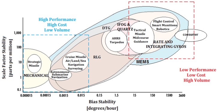
Scale factor stability (i.e., the accuracy of the gyroscope in monitoring the sensed angular velocity), expressed in parts per million (ppm), as a function of the bias stability (intrinsically dependent on the gyroscope technology) for Mechanical Gyroscopes, Ring Laser Gyroscopes (RLG), Interferometric Fiber-Optic gyroscopes (IFOG), Quartz, Dynamically Tuned Gyroscopes (DTG), Rate and Integrating Gyroscopes and MEMS.
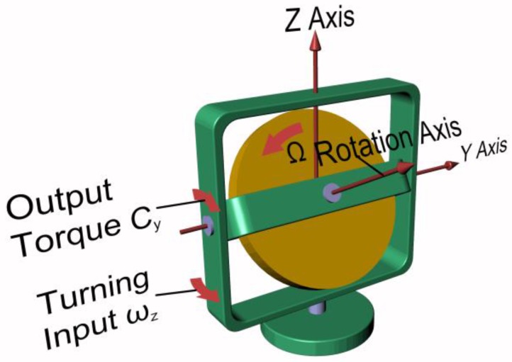
Elements of a mechanical gyroscope and main parameters.
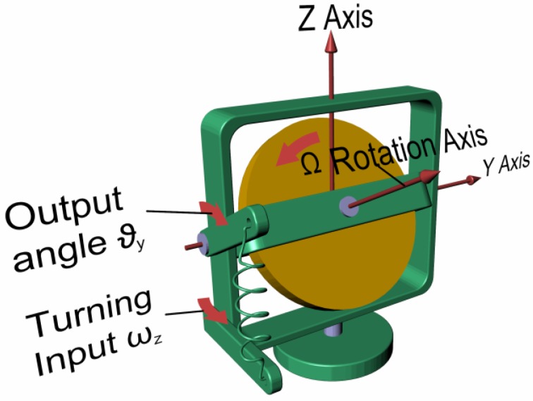
Mechanical rate gyroscope.
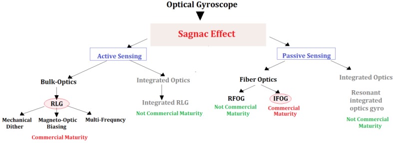
Classes of optical gyroscopes.
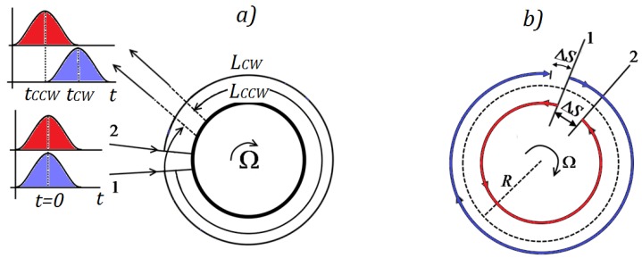
In a disk rotating with a clockwise (CW) angular velocity: (a) different rotation induced optical paths of the clockwise and counter-clockwise (CCW) optical beams, LCW and LCCW, respectively; and (b) identical difference, ΔS, between the rotation induced optical paths of the clockwise and counter-clockwise optical beam, and the standing optical path.
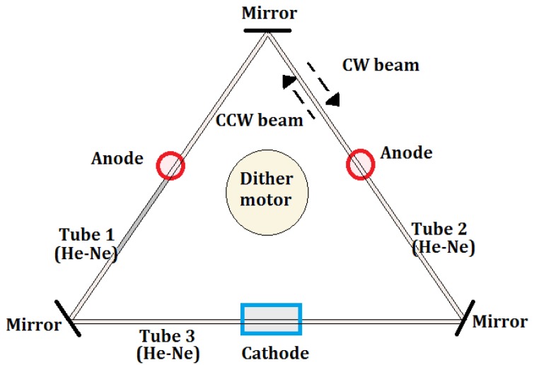
RLG made by a triangular optical resonator.
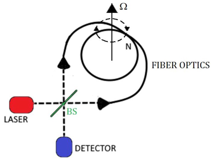
IFOG configuration.
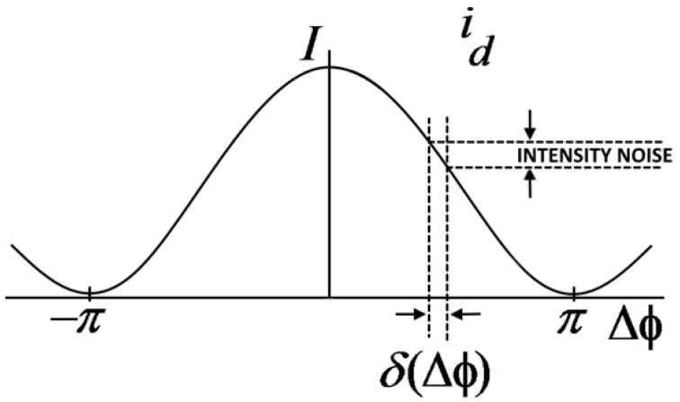
Intensity I of the output photo-current of the photo-detector.
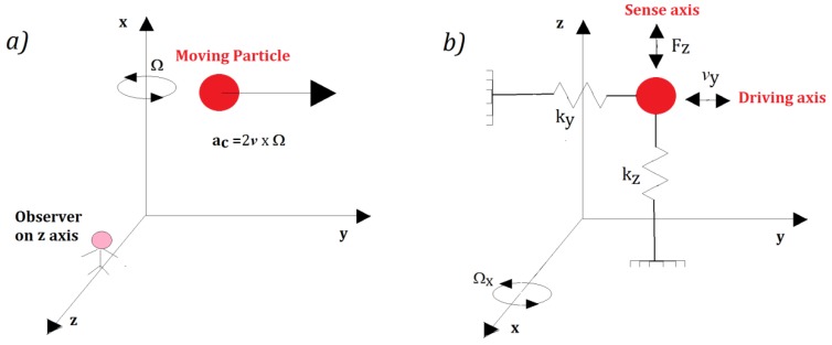
(a) Coriolis acceleration (ac) acting on a moving particle; and (b) mass-spring model of a MEMS gyroscope.
References
-
- NASA. [(accessed on 24 June 2017)]; Available online: https://solarsystem.nasa.gov/news/2005/03/14/brief-history-of-gyroscopes.
-
- Elliott-Laboratories . The Anschutz Gyro-Compass and Gyroscope Engineering. Wexford College Press; Kiel, Germany: 2003. pp. 7–24.
-
- Honeywell. [(accessed on 24 June 2017)]; Available online: https://aerospace.honeywell.com/en/products/navigation-and-sensors/inert....
-
- King A.D. Inertial Navigation—Forty Years of Evolution. GEC Rev. 1998;13:140–149.
-
- Inertial Labs. [(accessed on 24 June 2017)]; Available online: https://inertiallabs.com/ahrs.html.
Publication types
LinkOut - more resources
Full Text Sources
Other Literature Sources
