Review
. 2017 Oct 25;117(20):12764-12850.
doi: 10.1021/acs.chemrev.7b00094. Epub 2017 Oct 9.

Functional and Biomimetic Materials for Engineering of the Three-Dimensional Cell Microenvironment

Affiliations
Review

Functional and Biomimetic Materials for Engineering of the Three-Dimensional Cell Microenvironment

Guoyou Huang et al. Chem Rev. .

Abstract

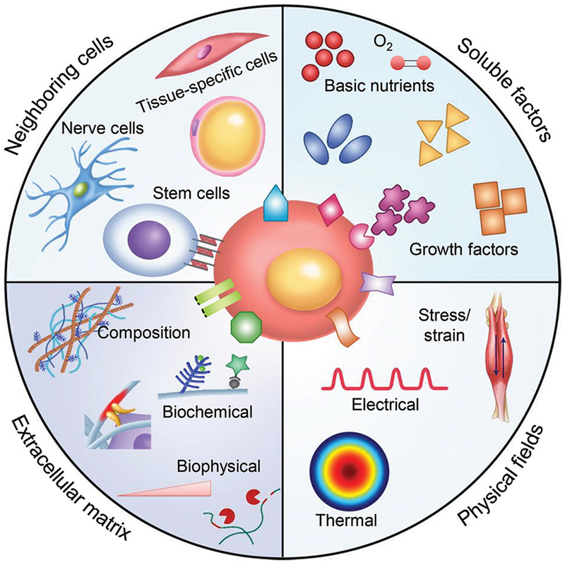
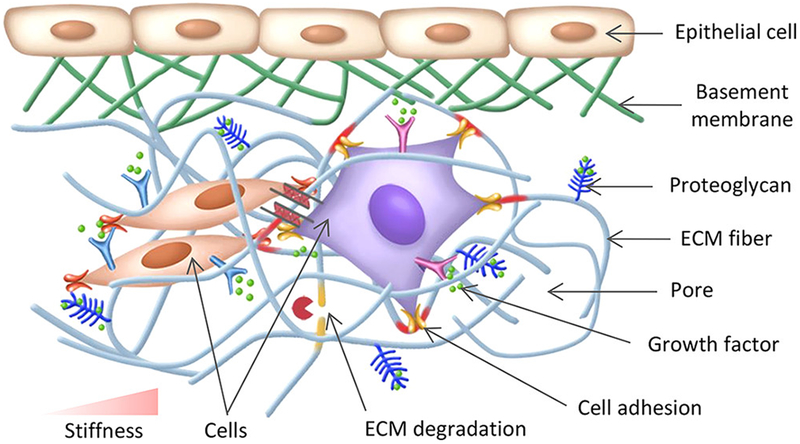
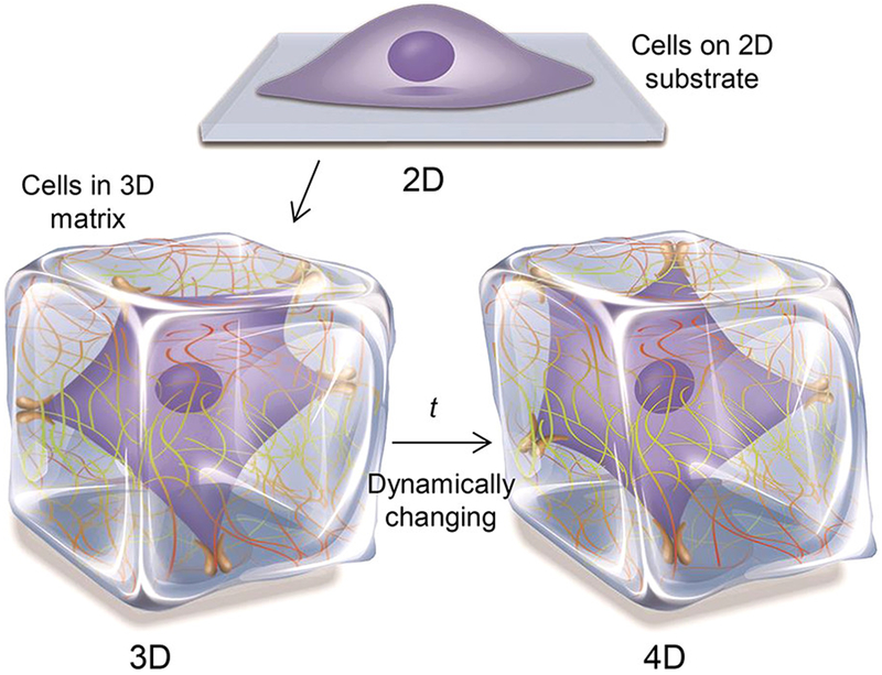
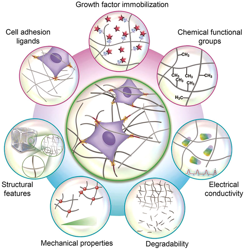
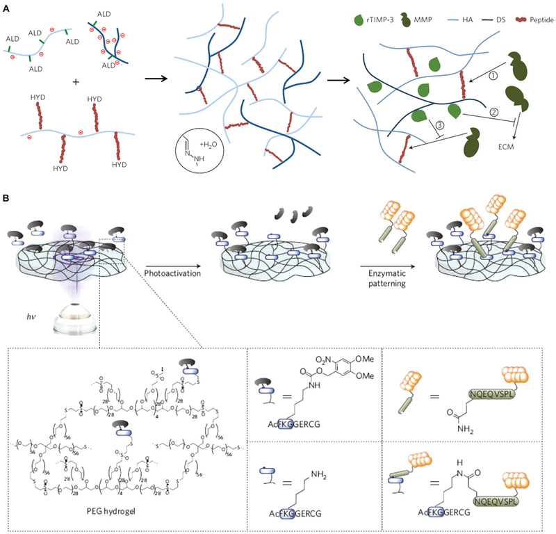
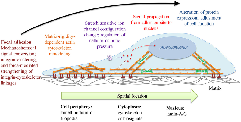
The cell microenvironment has emerged as a key determinant of cell behavior and function in development, physiology, and pathophysiology. The extracellular matrix (ECM) within the cell microenvironment serves not only as a structural foundation for cells but also as a source of three-dimensional (3D) biochemical and biophysical cues that trigger and regulate cell behaviors. Increasing evidence suggests that the 3D character of the microenvironment is required for development of many critical cell responses observed in vivo, fueling a surge in the development of functional and biomimetic materials for engineering the 3D cell microenvironment. Progress in the design of such materials has improved control of cell behaviors in 3D and advanced the fields of tissue regeneration, in vitro tissue models, large-scale cell differentiation, immunotherapy, and gene therapy. However, the field is still in its infancy, and discoveries about the nature of cell-microenvironment interactions continue to overturn much early progress in the field. Key challenges continue to be dissecting the roles of chemistry, structure, mechanics, and electrophysiology in the cell microenvironment, and understanding and harnessing the roles of periodicity and drift in these factors. This review encapsulates where recent advances appear to leave the ever-shifting state of the art, and it highlights areas in which substantial potential and uncertainty remain.


Figures

Figure 1.
Figure 1.
Schematic illustration of the main components of the cell microenvironment. Key components of the cell microenvironment include neighboring cells, soluble factors, the ECM, and biophysical fields (e.g., stress and stain, electrical, and thermal fields). Among these, the ECM not only serves as a structural support for cells to reside within but also provides diverse biochemical and biophysical cues for regulating cell behaviors.
Figure 2.
Figure 2.
Electron microscopic overview of a rat left ventricular myocardial capillary. The capillary was stained with Alcian blue 8GX. The inset is a detailed picture of glycocalyx on the capillary. Reprinted with permission from ref . Copyright 2003 Wolters Kluwer.
Figure 3.
Figure 3.
Schematic representation of cell–ECM interactions. Cells are surrounded by abundant ECM, which provides diverse biochemical cues (e.g., cell adhesion ligands and growth factor immobilization) and biophysical cues (e.g., structural features, mechanical stiffness, and degradation) for guiding cell behaviors.
Figure 4.
Figure 4.
Schematic of engineering the cell microenvironment from 2D to 3D and 4D.
Figure 5.
Figure 5.
Biomimetic material design considerations for engineering the 3D cell microenvironment. The design considerations can be generally divided into two classes, i.e., biochemical (e.g., cell adhesion ligands, soluble factor immobilization, and chemical functional groups) and biophysical design considerations (e.g., structural features, mechanical properties, degradability, and electrical conductivity).
Figure 6.
Figure 6.
Classification of hydrogel-based biomimetic materials for engineering the 3D cell microenvironment. Most biomimetic materials used for engineering the 3D cell microenvironment are based on hydrogels, which can be classified into naturally derived, synthetic, and hybrid hydrogels, according to their origins and compositions.
Figure 7.
Figure 7.
Photopatterning full-length proteins in hydrogels. The protein of interest is first functionalized with NHS-ortho-nitrobenzyl (o-NB)-CHO and then incorporated into SPAAC-based hydrogels via photomediated oxime ligation. Upon further light exposure, the photoscissile o-NB moieties undergo photocleavage, leading to the removal of linked proteins. Reprinted with permission from ref . Copyright 2015 Nature Publishing Group.
Figure 8.
Figure 8.
Photopatterning hydrogels with cell adhesion peptides. (A) Maleimide-functionalized biomolecules (e.g., GRGDS) are incorporated into agarose hydrogels modified with 2-NB-protected cysteine. Reprinted with permission from ref . Copyright 2004 Nature Publishing Group. (B) PEG-based hydrogels are prepared through a copper-free SPAAC click reaction. Biochemical molecules (e.g., RGD) can be subsequently patterned in the hydrogels by an orthogonal thiol–ene photocoupling reaction. Reprinted with permission from ref . Copyright 2009 Nature Publishing Group.
Figure 9.
Figure 9.
Growth factor immobilization in hydrogels. (A) HA hydrogels are modified with dextran sulfate (a heparin mimetic) for sequestering rTIMP-3. The hydrogels can release rTIMP-3 in response to locally elevated MMP levels in vivo. Reprinted with permission from ref . Copyright 2014 Nature Publishing Group. (B) Enzymatic hydrogel photopatterning with bioactive signaling proteins. Transglutaminase factor XIII is rendered photosensitive by masking its active site with a photolabile cage group and then incorporated into PEG-based hydrogels. Biologically relevant signaling proteins are subsequently patterned into hydrogels through local light-activated enzymatic cross-linking. Reprinted with permission from ref . Copyright 2013 Nature Publishing Group.
Figure 10.
Figure 10.
Small-molecule chemical groups used for modifying PEG hydrogels, including amino, acid, t-butyl, phosphate, and fluoro groups. Reprinted with permission from ref . Copyright 2008 Nature Publishing Group.
Figure 11.
Figure 11.
Schematic of the structural design aspects of biomimetic materials that can be classified as macroscale, microscale, and nanoscale design aspects. Macroscale design is related to external structure characteristics, such as overall shape and size. Microscale design is related to the characteristics of microwells, micropores, microchannels, microgels, and microfibers in hydrogels. Nanoscale design is related to the characteristics of nanofibers and nanoparticles that compose hydrogels.
Figure 12.
Figure 12.
Fabrication of microfluidic hydrogels for perfusion cell culture. (A) Schematic of the fabrication of microfluidic cell-laden hydrogels using a helical spring as a template. Reprinted with permission from ref . Copyright 2012 Wiley Periodicals, Inc. (B) Schematic of the fabrication of microfluidic cell-laden hydrogels based on sacrificial printed carbohydrate-glass fibers. Reprinted with permission from ref . Copyright 2012 Nature Publishing Group.
Figure 13.
Figure 13.
Chinese-noodle-inspired fabrication of hydrogel microfibers for engineering muscle myofibers. (A) Schematic of the high-throughput generation of cell-laden hydrogel microfibers by squeezing a cell-laden hydrogel block through a sieve. (B) Schematic of the magnetically actuated stretching of cell-laden hydrogel microfibers for generating functional myofibers. Reprinted with permission from ref . Copyright 2015 WILEY-VCH Verlag GmbH & Co. KGaA, Weinheim.
Figure 14.
Figure 14.
Generation of nanofibers through the self-assembly of collagen-mimetic peptide amphiphiles. (A) Molecular structure of collagen-mimetic peptide amphiphiles. (B) Self-assembly process. Reprinted with permission from ref . Copyright 2011 American Chemical Society.
Figure 15.
Figure 15.
Control over nanoscale hydrogel mechanics. (A) Decreasing the self-assembly temperature results in collagen fibril bundling and increased fiber diameter (a), which contributes to increased local fiber stiffness (b). Scale bars: μm. Reprinted with permission from ref . Copyright 2015 Nature Publishing Group. (B) AuNRs are mixed with collagen to form nanocomposite hydrogels (a–c). The incorporation of AuNRs results in increased nanoscale hydrogel stiffness without impacting the bulk mechanical properties (d). Scale bars: 500 nm for (c, d). Reprinted with permission from ref . Copyright 2016 WILEY-VCH Verlag GmbH & Co. KGaA, Weinheim.
Figure 16.
Figure 16.
Nonlinear elasticity of hydrogels. (A) Differential modulus-stress plot showing the stress-stiffening behavior of some biopolymers. (B) Synthesis of polyisocyanopeptides with varying polymer chain lengths (mean polymer length) by adjusting the molar ratio of catalyst to monomer, which results in (C) different mean critical stress levels. Reprinted with permission from ref . Copyright 2015 Nature Publishing Group.
Figure 17.
Figure 17.
Engineering the viscoelasticity of hydrogels to mimic that of living tissues. (A) Viscoelastic behaviors of some living tissues and hydrogels. (B) Schematic of designing alginate hydrogels with varying stress-relaxation rates by the combinatorial use of different molecular weight alginate macromers, ionic cross-linking densities, and short PEG spacers covalently linked to the alginate backbone. (C) Stress-relaxation behaviors of alginate hydrogels. (D) The stress-relaxation time scale (a), initial elastic modulus (b), and initial elastic modulus after 1-day and 7-day cultures (c), and the dry mass (d) of alginate hydrogels. Reprinted with permission from ref . Copyright 2016 Nature Publishing Group.
Figure 18.
Figure 18.
Spatial modulation of hydrogel mechanical properties. (A) Schematic of photopatterning hydrogels with bar-coded (a) and gradient (b) stiffness. (B) Schematic of the microfluidic fabrication of hydrogels with a mechanical gradient (a) and core–shell (softer-stiffer) hydrogel particles (b).
Figure 19.
Figure 19.
Temporal modulation of hydrogel mechanical properties. (A) A slow Michael-type addition reaction to cross-link thiolated HA with PEGDA. The reaction dynamics, and thus the stiffening process, can be controlled by changing the PEGDA molecular weight. (B) Stiffening of HA hydrogels through a sequential cross-linking strategy. HA macromers are modified with methacrylate and partially cross-linked with DTT via Michael-type addition reactions. The initial hydrogels are then UV-cross-linked to induce stiffening. (C) Light-mediated softening of a photodegradable PEG-based hydrogel. Photolabile groups are incorporated into di(meth)acrylated PEG macromers, which are then cross-linked to form photodegradable hydrogels. Upon exposure to UV light, the cross-linkages are cleaved, resulting in hydrogel softening. Reprinted with permission from ref . Copyright 2012 Nature Publishing Group.
Figure 20.
Figure 20.
Schematic of hydrogels with reversibly modulated mechanical properties. (A) Ca2+-cross-linked alginate-based hydrogel. Reprinted with permission from ref . Copyright 2010 WILEY-VCH Verlag GmbH & Co. KGaA, Weinheim. (B) Thermal-responsive PNIPAAm-based hybrid hydrogel. Reprinted with permission from ref . Copyright 2015 WILEY-VCH Verlag GmbH & Co. KGaA, Weinheim. (C) pH-sensitive triblock hydrogel. Reprinted with permission from ref . Copyright 2011 American Chemical Society. (D) DNA-cross-linked PA hydrogel. Reprinted with permission from ref . Copyright 2012 Biomedical Engineering Society. (E) Supramolecular hydrogel with host–guest interactions. Reprinted with permission from ref . Copyright 2016 Royal Society of Chemistry.
Figure 21.
Figure 21.
Cellular mechanosensitive system. The cell-adhesions, myosin-filaments system, tension-sensitive ion channel, and nuclear lamina both can act as the cellular mechanosensors which are distributed from cell–ECM interfaces to cell nuclear.
Figure 22.
Figure 22.
Adaptable hydrogels. (A) Comparison of a reversibly cross-linked, adaptable hydrogel with a permanently cross-linked, degradable hydrogel. Reprinted with permission from ref . Copyright 2015 WILEY-VCH Verlag GmbH & Co. KGaA, Weinheim. (B) Comparison of an adaptable hydrogel based on sliding cross-linkages with a covalently cross-linked hydrogel. Reprinted with permission from ref . Copyright 2015 WILEY-VCH Verlag GmbH & Co. KGaA, Weinheim.
Figure 23.
Figure 23.
Hydrogels with different degradation mechanisms. (A) An enzymatically degradable PEG-based hydrogel. Vinyl sulfone-modified multiarm PEG macromers are functionalized with cell adhesion peptides and then cross-linked with bis-cysteine MMP-sensitive peptides to form enzyme-degradable hydrogels. Reprinted with permission from ref . Copyright 2003 Nature Publishing Group. (B) Molecular structure of a hydrolytically degradable triblock copolymer, i.e., PCLA-PEG-PCLA. Reprinted with permission from ref . Copyright 2011 Elsevier, Ltd. All rights reserved. (C) A photodegradable PEG-based hydrogel. Such a photodegradable hydrogel system has been used for engineering softening hydrogels. Reprinted with permission from ref . Copyright 2009 American Association for the Advancement of Science.
Figure 24.
Figure 24.
Electrically conductive hydrogels. (A) PPy-chitosan hydrogel. Reprinted with permission from ref . Copyright 2015 American Heart Association, Inc. (B) AuNP-alginate hydrogel. Reprinted with permission from ref . Copyright 2011 Nature Publishing Group. (C) CNT-GelMA hydrogel. Reprinted with permission from ref . Copyright 2013 American Chemical Society. (D) GO-MeTro hydrogel. Reprinted with permission from ref . Copyright 2016 WILEY-VCH Verlag GmbH & Co. KGaA, Weinheim.
Figure 25.
Figure 25.
Schematic of a microelectronic cardiac patch. Such electronic scaffolds enable the electrically controlled release of biomolecules, the electrical stimulation of cells and engineered tissues, and the electrical sensing of cell responses and engineered tissue performances. Reprinted with permission from ref . Copyright 2016 Nature Publishing Group.
Figure 26.
Figure 26.
Conductivities of conductive biomimetic materials as a function of concentrations.
Figure 27.
Figure 27.
Independent control over biomimetic material properties. (A) Microfabrication. By varying the height of PDMS microposts but keeping the diameter the same, the effective stiffness (or spring constant) of the microposts is tuned independent of adhesion-ligand density and surface chemical properties. Reprinted with permission from ref . Copyright 2010 Nature Publishing Group. (B) Chemical modification. Cysteine-containing peptides are incorporated into PEG-based hydrogels via a thiol–ene click reaction with independent control over the stiffness and adhesion-ligand density. Reprinted with permission from ref . Copyright 2010 American Chemical Society. (C) Composition change. PA hydrogels are fabricated with independently controlled stiffness and pore size (or porosity) by adjusting the acrylamide/bis-acrylamide ratio. Scale bars: 50 μm. Reprinted with permission from ref . Copyright 2014 Nature Publishing Group. (D) Cross-linking regulation. The stiffness of IPN hydrogels made from a reconstituted basement membrane matrix and alginate is tuned by simply increasing the Ca2+ concentration used for cross-linking alginate independent of the pore structure and adhesion-ligand density. Reprinted with permission from ref . Copyright 2014 Nature Publishing Group.
Figure 28.
Figure 28.
Cardiac regeneration using cell aggregate-laden hydrogel vehicles. (A) Schematic of hydrogel injection at different locations for repairing myocardial infarction (MI) in a mouse disease model. (B) Overview of the bioinspired process for fabricating murine ESC aggregate-laden alginate-chitosan micromatrix (ACM) vehicles together with live/dead staining images. Scale bar: 100 μm. (C) Gross images of a normal heart and MI hearts administered five different treatments (ACM-A, cell aggregates with ACM encapsulation; Bare-A, bare predifferentiated aggregate). Arrows indicate granulomas generated in single-cell (Single)- and Bare-A-treated mice. Scale bar: 3 mm. (D) Survival of the mouse disease model at 4 weeks; the ACM-A group exhibited significantly higher survival than all the other groups. (E) Ejection fraction results; the ACM-A treatment significantly enhanced heart function after MI. Reprinted with permission from ref . Copyright 2016 Nature Publishing Group.
Figure 29.
Figure 29.
Bone regeneration using cell-laden GelMA microspheres. (A) Schematic illustration for the fabrication of cell-laden GelMA microspheres using a photo-cross-linking-microfluidic method, and in vitro and in vivo applications for osteogenesis and bone regeneration in a rabbit model. (B) Alizarin red staining results of cell-laden GelMA microspheres after (a) 1, (b) 2, (c) 3, and (d) 4 weeks of culture for in vitro osteogenesis. Scale bar: 100 μm. (C) Histomorphometric results (%) of new bone (left) and osteoid (right) formation. Reprinted with permission from ref . Copyright 2016 WILEY-VCH Verlag GmbH & Co. KGaA, Weinheim.
Figure 30.
Figure 30.
Heart-on-a-chip. (A) Schematic illustration of a heart-on-a-chip fabricated by a multimaterial 3D printing technique. (B) Overview of a printed chip, and a confocal microscopy image of immunostained cardiac tissue. Blue, DAPI nuclear stain. White, α-actinin. Scale bars: 10 μm. (C) Images of immunostained laminar cardiac tissues on chip cantilevers on day 2 (left) and day 28 (right), respectively. Blue, DAPI nuclear stain. White, α-actinin. Scale bars: 10 μm. (D) Contractile twitch stress generated by laminar cardiac tissues on day 2 (left) and day 28 (right), respectively. (E) A modified chip cantilever with supporting thicker laminar cardiac tissue (left), and immunostained thicker laminar cardiac tissue (right). Blue, DAPI nuclear stain. White, α-actinin. Red, actin. Scale bars: 30 μm for (1), and 10 μm for (2). (F) Dose–response curve for verapamil (left) and isoproterenol (right). Reprinted with permission from ref . Copyright 2016 Nature Publishing Group.
Figure 31.
Figure 31.
Breathing lung-on-a-chip. (A) Schematic illustration of the design of the breathing lung-on-a-chip. (B) Sketch diagram of the physical stretching process of the alveolar–capillary interface in the lungs during inhalation. (C) Cross-sectional view of microfluidic chip. Scale bar: 200 μm. (D) Overview images of a chip device. (E) 3D confocal reconstruction of the epithelial–endothelial tissue interface generated on the chip. (F) Functional tissue membrane generated 15% strain in cells. (G) Toxicological study of silica nanoparticles based on the lung chip. Left, endothelial expression of intercellular adhesion molecule 1 (ICAM-1) and neutrophil adhesion in the lower channel. Right, mechanical strain and silica nanoparticles synergistically increased the expression of ICAM-1. Scale bar: 50 μm. (H) Mechanical strain (10%) promoted the cellular uptake of polystyrene nanoparticles (100 nm). Internalized nanoparticles are indicated with arrows. (I) Schematic illustration of mimicking nanoparticle transportation across the alveolar–capillary interface with the lung chip. Reprinted with permission from ref . Copyright 2010 American Association for the Advancement of Science.

References

    1. Scadden DT The stem-cell niche as an entity of action. Nature 2006, 441, 1075–1079. - PubMed
    1. Discher DE; Mooney DJ; Zandstra PW Growth factors, matrices, and forces combine and control stem cells. Science 2009, 324, 1673–1677. - PMC - PubMed
    1. Scadden David T. Nice neighborhood: Emerging concepts of the stem cell niche. Cell 2014, 157, 41–50. - PMC - PubMed
    1. Humphrey JD; Dufresne ER; Schwartz MA Mechanotransduction and extracellular matrix homeostasis. Nat. Rev. Mol. Cell Bio 2014, 15, 802–812. - PMC - PubMed
    1. Lu P; Weaver VM; Werb Z The extracellular matrix: A dynamic niche in cancer progression. J. Cell Biol 2012, 196, 395–406. - PMC - PubMed

MeSH terms