. 2018 May;36(5):1508-1518.
doi: 10.1002/jor.23771. Epub 2017 Nov 22.

Additive manufactured push-fit implant fixation with screw-strength pull out

Affiliations

Additive manufactured push-fit implant fixation with screw-strength pull out

Richard J van Arkel et al. J Orthop Res. 2018 May.

Abstract

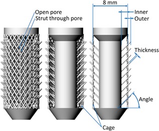
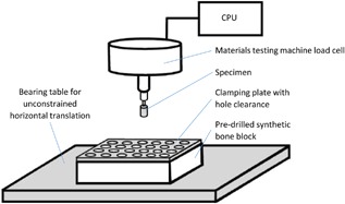
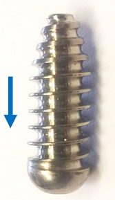
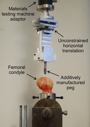
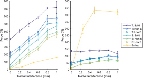
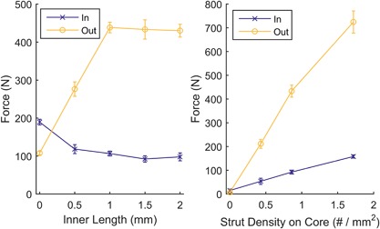
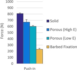
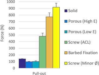
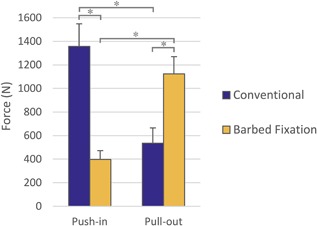
Additive manufacturing offers exciting new possibilities for improving long-term metallic implant fixation in bone through enabling open porous structures for bony ingrowth. The aim of this research was to investigate how the technology could also improve initial fixation, a precursor to successful long-term fixation. A new barbed fixation mechanism, relying on flexible struts was proposed and manufactured as a push-fit peg. The technology was optimized using a synthetic bone model and compared with conventional press-fit peg controls tested over a range of interference fits. Optimum designs, achieving maximum pull-out force, were subsequently tested in a cadaveric femoral condyle model. The barbed fixation surface provided more than double the pull-out force for less than a third of the insertion force compared to the best performing conventional press-fit peg (p < 0.001). Indeed, it provided screw-strength pull out from a push-fit device (1,124 ± 146 N). This step change in implant fixation potential offers new capabilities for low profile, minimally invasive implant design, while providing new options to simplify surgery, allowing for one-piece push-fit components with high levels of initial stability. © 2017 The Authors. Journal of Orthopaedic Research® Published by Wiley Periodicals, Inc. on behalf of the Orthopaedic Research Society. J Orthop Res 36:1508-1518, 2018.

Keywords: 3D printing; initial implant stability; minimally invasive implants; porous implants; press-fit.


Figures

Figure 1
Figure 1
Diagram of the barbed fixation implant. From left to right the cage and front and rear fixation struts have been progressively removed to expose the design. Properties that effect the strut flexibility (inner and outer length, width, and angle) are highlighted, as are design features such as projecting the strut through a pore.
Figure 2
Figure 2
A schematic drawing of the synthetic bone tests highlighting the main features of the test set‐up.
Figure 3
Figure 3
The ACL interference screw tested. The arrow indicates the direction of push out.
Figure 4
Figure 4
The testing set‐up for the cadaveric knee condyle tests.
Figure 5
Figure 5
Straight sided (left) and tapered (middle) solid press‐fit pegs. An example surface roughness measurement (right) is also shown.
Figure 6
Figure 6
The force required for push in (left) and pull out (right) for different interference fits in synthetic bone (N = 4 per point). With increasing interference, push‐in force increased, while pull‐out force increased before reaching a maximum. T, Tapered cylinder; S, Straight sided cylinder; Solid, Solid implant; Low E, 600 MPa porous implant; High E, 2.6 GPa porous implant; Barbed, Baseline version of barbed fixation implant with varying outer length.
Figure 7
Figure 7
Low effective modulus (left) and high effective modulus (right) straight sided (top) and tapered (bottom) porous press‐fit pegs.
Figure 8
Figure 8
The optimized barbed fixation specimen deconstructed (left and middle) to demonstrate how the design works, and as tested (right).
Figure 9
Figure 9
(a) Push‐in and pull‐out forces for different inner length barbed fixation designs. Allowing the struts to project from within the implant, through open pores, increased the pull‐out forces while decreasing the push‐in force; the maximum was reached through the strut hitting the cage. (b) Push‐in and pull‐out forces for increased strut density. Increasing the strut density effectively increased interference, increasing push in and pull out. N = 4 for all points, tests performed in synthetic bone.
Figure 10
Figure 10
Push‐in force comparison for optimum the barbed fixation design and the tapered press‐fit pegs with their optimum interference in synthetic bone (N = 4 per design). The barbed fixation more than halved push‐in forces.
Figure 11
Figure 11
Pull‐out force comparison between the optimum barbed fixation design, the tapered press‐fit pegs with their optimum interference and an interference screw at the recommended hole size for ACL surgery and with a hole sized to its minor diameter in synthetic bone (N = 4 per design). The barbed fixation surface required >5× the pull out compared to press‐fit pegs and achieved pull out comparable to an interference screw.
Figure 12
Figure 12
Comparison between optimized conventional and barbed fixation peg designs in cadaveric knee condyles (N = 8 per design). The human bone tests confirmed results from the sawbones model: The barbed fixation design offered higher pull‐out force for less push‐in effort. An asterisk (*) indicates p < 0.001.

Similar articles

Cited by

References

    1. Mall NA, Chalmers PN, Moric M, et al. 2014. Incidence and trends of anterior cruciate ligament reconstruction in the United States. Am J Sports Med 42:2363–2370. - PubMed
    1. National Joint Registry for England and Wales. 2016. 13th Annual Report.
    1. Maradit Kremers H, Larson DR, Crowson CS, et al. 2015. Prevalence of total hip and knee replacement in the United States. J Bone Joint Surg Am 97:1386–1397. - PMC - PubMed
    1. New Zeland Joint Registry. 2016. 17th Annual Report.
    1. Chapman JR, Harrington RM, Lee KM, et al. 1996. Factors affecting the pullout strength of cancellous bone screws. J Biomech Eng 118:391–398. - PubMed

Publication types