

Unconventional two-dimensional vibrations of a decorated carbon nanotube under electric field: linking actuation to advanced sensing ability
- PMID: 29044124
- PMCID: PMC5647406
- DOI: 10.1038/s41598-017-12647-2
Unconventional two-dimensional vibrations of a decorated carbon nanotube under electric field: linking actuation to advanced sensing ability
Abstract
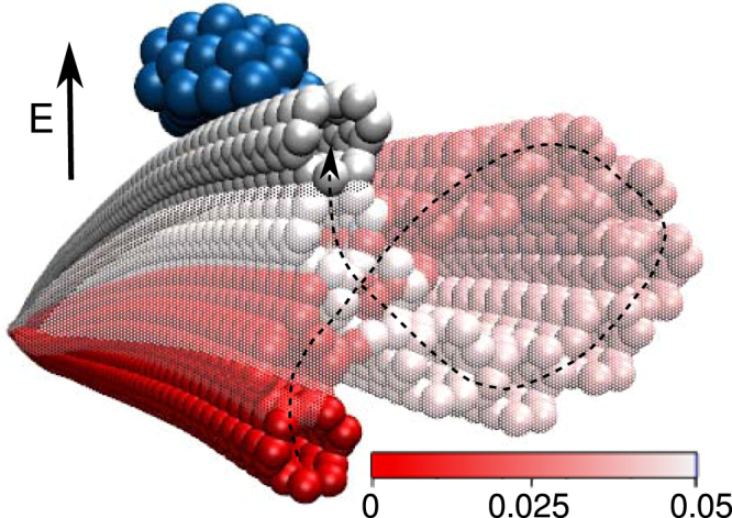
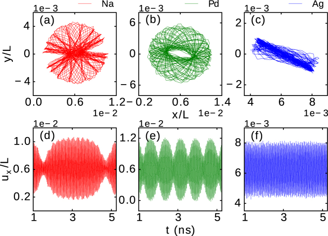
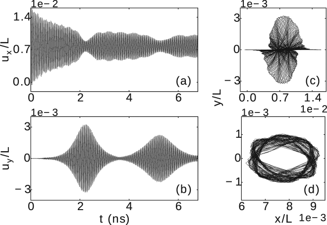
We show that a carbon nanotube decorated with different types of charged metallic nanoparticles exhibits unusual two-dimensional vibrations when actuated by applied electric field. Such vibrations and diverse possible trajectories are not only fundamentally important but also have minimum two characteristic frequencies that can be directly linked back to the properties of the constituents in the considered nanoresonator. Namely, those frequencies and the maximal deflection during vibrations are very distinctively dependent on the geometry of the nanotube, the shape, element, mass and charge of the nanoparticle, and are vastly tunable by the applied electric field, revealing the unique sensing ability of devices made of molecular filaments and metallic nanoparticles.
Conflict of interest statement
The authors declare that they have no competing interests.
Figures


Similar articles
-
Ag nanoparticles decorated TiO2 nanotube arrays for ultrasensitive gas sensing.J Nanosci Nanotechnol. 2013 Feb;13(2):1453-5. doi: 10.1166/jnn.2013.6033. J Nanosci Nanotechnol. 2013. PMID: 23646659
-
Novel in-situ decoration of single-walled carbon nanotube transistors with metal nanoparticles.J Nanosci Nanotechnol. 2010 Jun;10(6):3890-4. doi: 10.1166/jnn.2010.2005. J Nanosci Nanotechnol. 2010. PMID: 20355385
-
Nanotechnological selection.Nanotechnology. 2013 Jan 18;24(2):020201. doi: 10.1088/0957-4484/24/2/020201. Epub 2012 Dec 14. Nanotechnology. 2013. PMID: 23242125
-
Carbon nanotube and graphene-based bioinspired electrochemical actuators.Adv Mater. 2014 Feb;26(7):1025-43. doi: 10.1002/adma.201303432. Epub 2013 Dec 12. Adv Mater. 2014. PMID: 24338697 Review.
-
Charged Metal Nanoparticles for Chemoelectronic Circuits.Adv Mater. 2019 Nov;31(45):e1804864. doi: 10.1002/adma.201804864. Epub 2019 Jan 27. Adv Mater. 2019. PMID: 30687979 Review.
Cited by
-
Navigation of Silver/Carbon Nanoantennas in Organic Fluids Explored by a Two-Wave Mixing.Nanomaterials (Basel). 2020 Sep 21;10(9):1886. doi: 10.3390/nano10091886. Nanomaterials (Basel). 2020. PMID: 32967106 Free PMC article.
References
-
- Sazanova, V. et al. Nat. 431, 284, 10.1038/nature02905 (2004).
-
- Sazonova, V. A. A Tunable Carbon Nanotube Resonator. Ph.D. thesis, Cornell University (2006).
-
- Sapmaz S, Blanter YM, Gurevich L, van der Zant HSJ. Carbon nanotubes as nanoelectromechanical systems. Phys. Rev. B. 2003;67:235414. doi: 10.1103/PhysRevB.67.235414. - DOI
-
- Frank, I. W., Tanenbaum, D. M., van der Zande, A. M. & McEuen, P. L. J. Vac. Sci. Technol. B25, 2558, 10.1116/1.2789446 (2007).
Publication types
LinkOut - more resources
Full Text Sources
Other Literature Sources
