

Review
doi: 10.3762/bjnano.8.200.
eCollection 2017.
Advances and challenges in the field of plasma polymer nanoparticles
Affiliations
- PMID: 29046847
- PMCID: PMC5629419
- DOI: 10.3762/bjnano.8.200
Item in Clipboard
Review
Advances and challenges in the field of plasma polymer nanoparticles
Beilstein J Nanotechnol.
.
Abstract
This contribution reviews plasma polymer nanoparticles produced by gas aggregation cluster sources either via plasma polymerization of volatile monomers or via radio frequency (RF) magnetron sputtering of conventional polymers. The formation of hydrocarbon, fluorocarbon, silicon- and nitrogen-containing plasma polymer nanoparticles as well as core@shell nanoparticles based on plasma polymers is discussed with a focus on the development of novel nanostructured surfaces.
Keywords: gas aggregation cluster source; nanocomposite; nanoparticles; plasma polymer; sputtering.
Figures
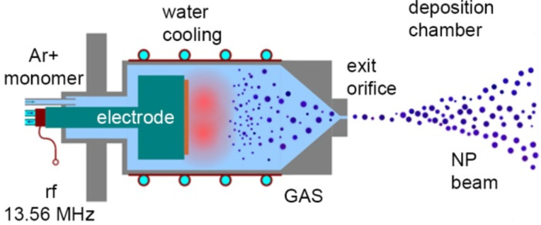
Scheme of a gas aggregation cluster source.
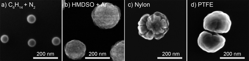
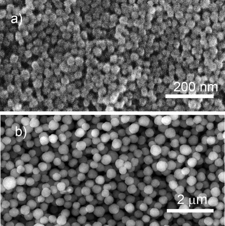
SEM images of different types of plasma polymer nanoparticles produced: a) by plasma polymerization of n-hexane in its mixture with N2; b) by plasma polymerization of HMDSO in its mixture with Ar (obtained in a similar manner as [53]); c) by RF magnetron sputtering of nylon in the Ar/N2 mixture (republished from [54] with permission IOP Publishing Ltd.); d) by RF magnetron sputtering of PTFE in Ar (obtained in a similar manner as [55]). The references shown here and in the following figures cite the authors’ previous works where similar (but not necessarily identical) data were presented; the unreferenced data represent the authors’ new material which has not been published yet, but which is necessary for a comparative analysis in this review.
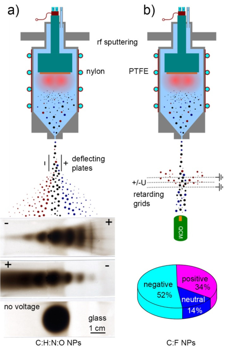
Experimental arrangements allowing estimation of plasma polymer NP charging: a) electrostatic plates used for deflection of charged nylon-sputtered NPs [66] by applying 200 V voltage of different polarity across the NP beam; b) electrostatic grids used for retardation of charged PTFE-sputtered NPs by applying 1000 V voltage of different polarity along the NP beam (obtained in a similar manner as [55]).
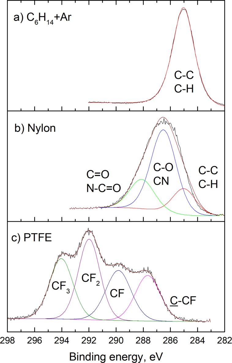
C 1s XPS of the NPs prepared a) by plasma polymerization of n-hexane in its mixture with Ar (total pressure 88 Pa, discharge power 40 W, C6H14 flow 1.2 sccm, Ar flow 12.2 sccm); b) by RF magnetron sputtering of nylon in the Ar/N2 3:1 mixture (obtained in a similar manner as [54]); c) by RF magnetron sputtering of PTFE in Ar (reprinted from [67], with permission from Elsevier).
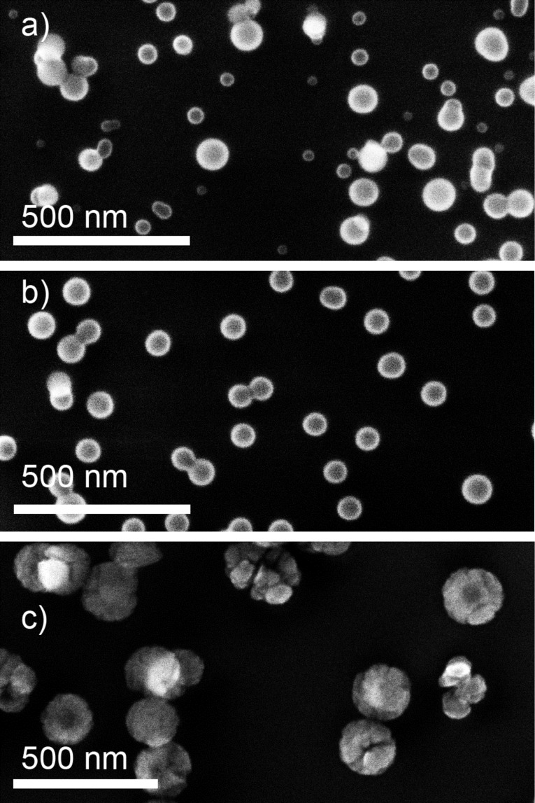
SEM images of nitrogen-containing NPs prepared a) by plasma polymerization of n-hexane in its mixture with Ar (total pressure 88 Pa, discharge power 40 W, C6H14 flow 1.2 sccm, Ar flow 12.2 sccm); b) by plasma polymerization of n-hexane in its mixture with N2 (total pressure 88 Pa, discharge power 40 W, C6H14 flow 1.2 sccm, N2 flow 12.2 sccm); c) by RF magnetron sputtering of nylon in the Ar/N2 3:1 mixture (obtained in a similar manner as [54]).
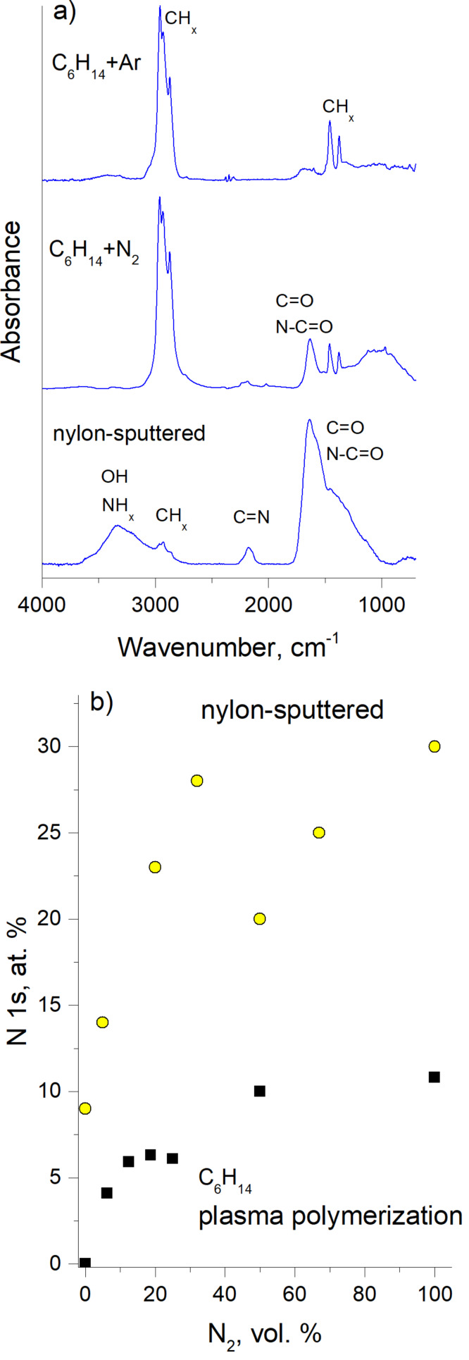
Chemical composition of nitrogen-containing NPs shown in Figure 5: a) FTIR spectra; b) the nitrogen content calculated from the XPS spectra as a function of the N2 concentration in the working gas.
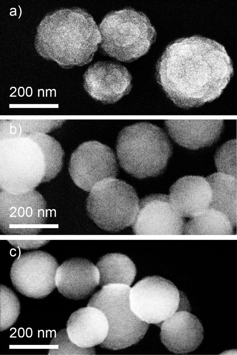
SEM images of NPs prepared by plasma polymerization of HMDSO mixed with Ar: a) without adding oxygen; b) with addition of oxygen at O2/HMDSO 1:1 ; c) with addition of oxygen at O2/HMDSO 5:1 (obtained in a similar manner as [53]). Total pressure is 55 Pa, discharge power is 30 W, HMDSO flow is 0.2 sccm, Ar flow is 2 sccm.
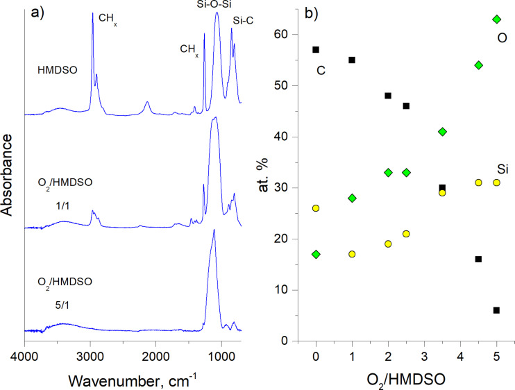
Chemical composition of the NPs shown in Figure 7: a) FTIR spectra b) the elemental content calculated from the XPS spectra as a function of the O2 concentration in the working gas (republished from [53] with permission of IOP Publishing Ltd.).
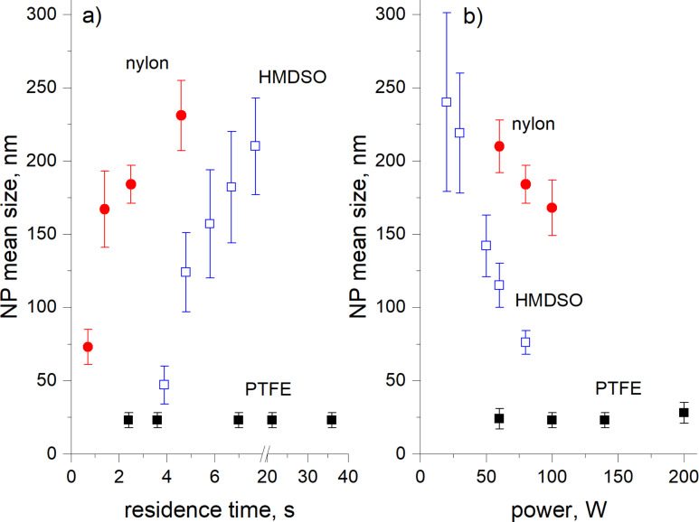
Mean diameter of nylon-sputtered, PTFE-sputtered and HMDSO plasma polymer NPs as a function of a) the residence time and b) the power of the discharge. The data are calculated from the results presented in [–5467].
SEM images of the PTFE-sputtered NPs deposited with different intensity of the magnetic field: a) 100 G, b) 250 G; Ar pressure is 100 Pa, flow rate is 9.2 sccm, residence time is 9 s, discharge power is 140 W, deposition time is 20 min; obtained in a similar manner as in [55].
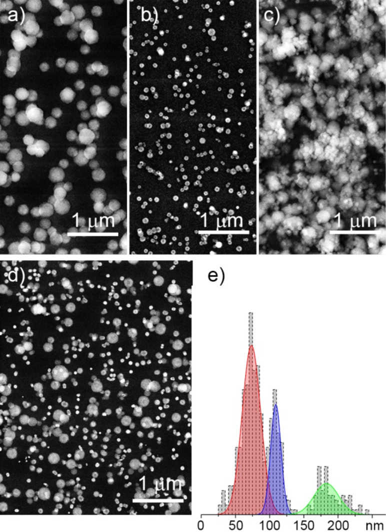
SEM images of NPs prepared by plasma polymerization of HMDSO in Ar: a) 220 nm NPs produced with 10 cm aggregation length; b) 40 nm NPs produced with 4 cm aggregation length; c) dual-scale structure produced by sequential deposition of a) and b); d) triple-scale structure produced by power-dependent sequential deposition of 200, 110 band 70 nm diameter NPs; e) size distribution histogram corresponding to d) (republished from [53] with permission of IOP Publishing Ltd.).
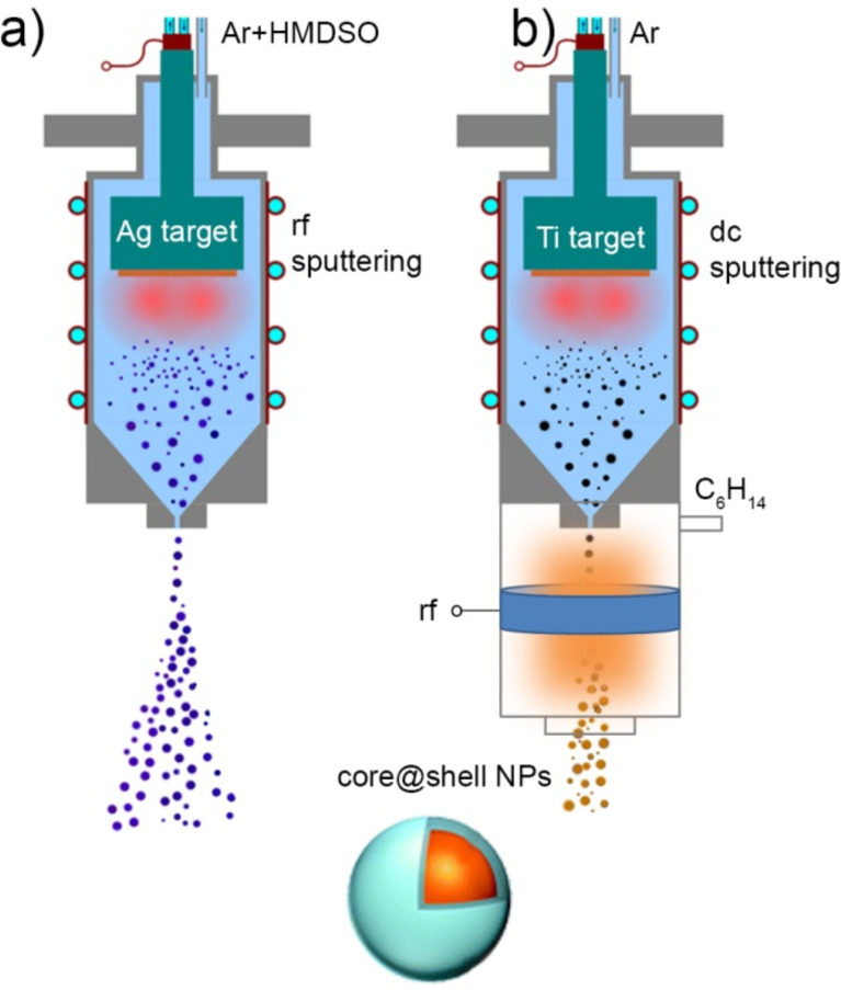
Scheme of synthesis of core@shell NPs by GAS: a) core@shell NPs are produced in the GAS by RF magnetron sputtering of Ag target in the gas mixture of Ar and HMDSO; b) metal NPs are produced by DC magnetron sputtering of Ti target in the GAS and then covered by shells of C/H plasma polymer in the auxiliary plasma reactor with external RF excitation.
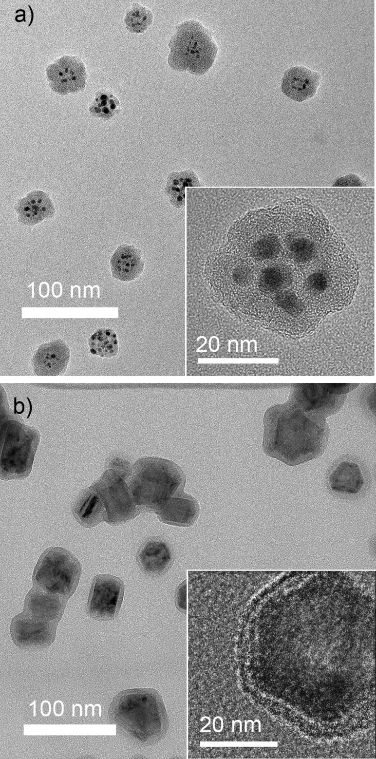
TEM images of core@shell NPs: a) Ag@HMDSO NPs prepared in configuration of Figure 12a (total pressure 190 Pa, discharge power 50 W, HMDSO flow 0.45 sccm, Ar flow 105 sccm); b) Ti@C/H NPs prepared in configuration of Figure 12b (Ar pressure/flow in the GAS is 40 Pa/4.0 sccm, DC 0.4 A, total pressure in the auxiliary plasma zone is 1 Pa (0.65 Pa of Ar and 0.35 Pa of C6H14), RF power is 10 W).
C/H NPs prepared in GAS by plasma polymerization of n-hexane and overcoated a) with a thin film of C/H plasma polymer (reprinted from [76], with permission from Elsevier) and b) with a Ti thin film (obtained in a similar manner as in [77]).
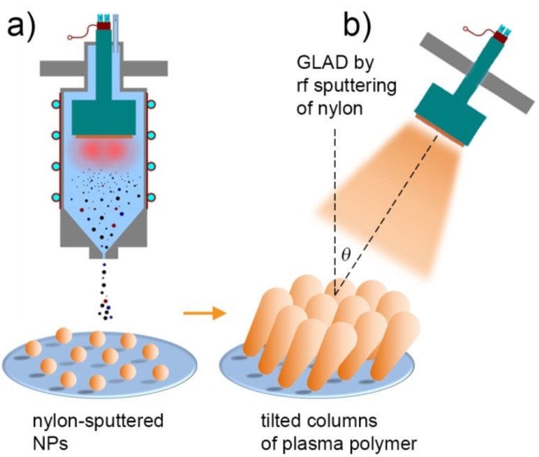
Scheme of GLAD: a) preseeding of substrates with nylon-sputtered NPs produced by GAS; b) GLAD of nylon-sputtered plasma polymer over the preseeded NPs.
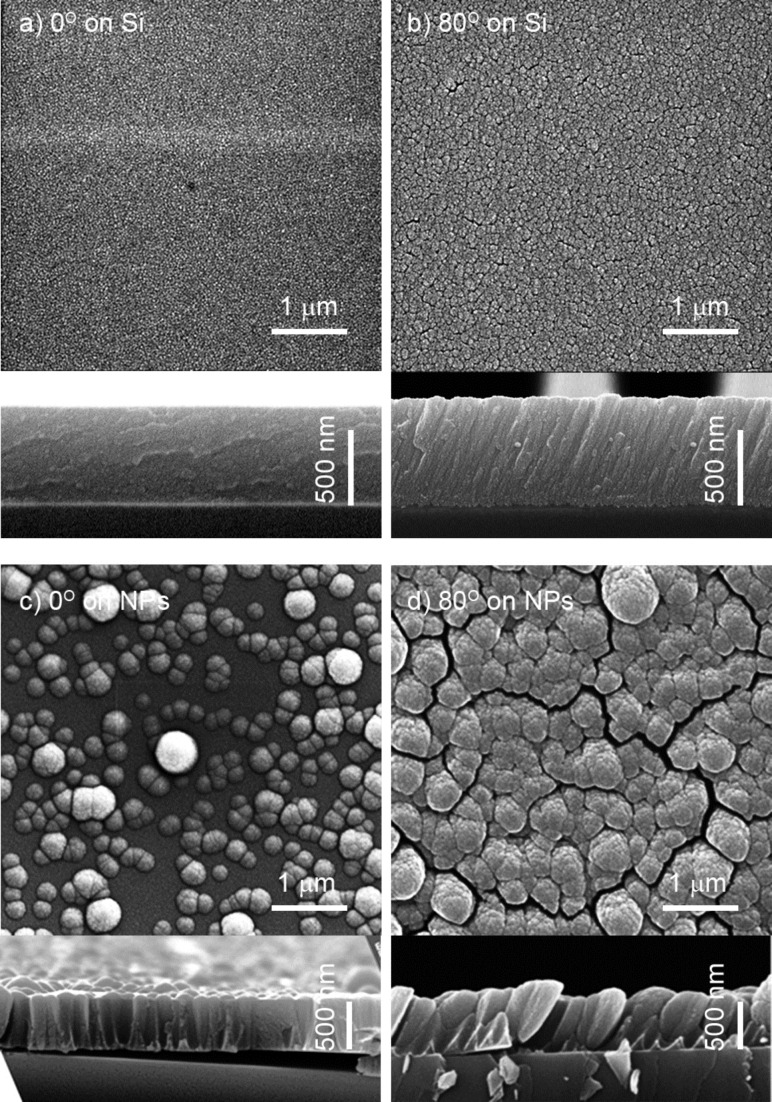
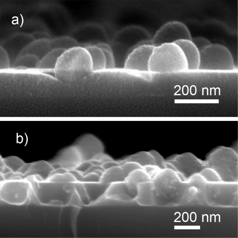
SEM images with combined top view and cross-sections of the deposits produced as a result of RF magnetron sputtering of nylon: a) normal deposition on blank Si substrate; b) GLAD at 80° on blank Si substrate; c) normal deposition over preseeded nylon-sputtered NPs; d) GLAD at 80° over preseeded nylon-sputtered NPs (reprinted from [81], with permission from Elsevier).
Similar articles
-
Magnetron Sputtering of Polymeric Targets: From Thin Films to Heterogeneous Metal/Plasma Polymer Nanoparticles.Materials (Basel). 2019 Jul 25;12(15):2366. doi: 10.3390/ma12152366. Materials (Basel). 2019. PMID: 31349580 Free PMC article.
-
Nanostructured Plasma Polymerized Fluorocarbon Films for Drop Coating Deposition Raman Spectroscopy (DCDRS) of Liposomes.Polymers (Basel). 2021 Nov 21;13(22):4023. doi: 10.3390/polym13224023. Polymers (Basel). 2021. PMID: 34833322 Free PMC article.
-
Core-shell molecularly imprinted polymer nanoparticles with assistant recognition polymer chains for effective recognition and enrichment of natural low-abundance protein.Acta Biomater. 2014 Feb;10(2):769-75. doi: 10.1016/j.actbio.2013.10.007. Epub 2013 Oct 17. Acta Biomater. 2014. PMID: 24140608
-
Synthesis of silica-polymer core-shell nanoparticles by reversible addition-fragmentation chain transfer polymerization.Chem Commun (Camb). 2013 Oct 14;49(80):9077-88. doi: 10.1039/c3cc45319g. Epub 2013 Sep 2. Chem Commun (Camb). 2013. PMID: 23999877 Review.
-
Antimicrobial Nanostructured Coatings: A Gas Phase Deposition and Magnetron Sputtering Perspective.Materials (Basel). 2020 Feb 8;13(3):784. doi: 10.3390/ma13030784. Materials (Basel). 2020. PMID: 32046363 Free PMC article. Review.
Cited by
-
Novel Dextran Coated Cerium Doped Hydroxyapatite Thin Films.Polymers (Basel). 2022 Apr 29;14(9):1826. doi: 10.3390/polym14091826. Polymers (Basel). 2022. PMID: 35566996 Free PMC article.
-
Mechanical time-of-flight filter based on slotted disks and helical rotor for measurement of velocities of nanoparticles.Sci Rep. 2021 Mar 19;11(1):6415. doi: 10.1038/s41598-021-85533-7. Sci Rep. 2021. PMID: 33742023 Free PMC article.
-
Magnetron Sputtering of Polymeric Targets: From Thin Films to Heterogeneous Metal/Plasma Polymer Nanoparticles.Materials (Basel). 2019 Jul 25;12(15):2366. doi: 10.3390/ma12152366. Materials (Basel). 2019. PMID: 31349580 Free PMC article.
-
Chitosan-Hydroxyapatite Composite Layers Generated in Radio Frequency Magnetron Sputtering Discharge: From Plasma to Structural and Morphological Analysis of Layers.Polymers (Basel). 2020 Dec 21;12(12):3065. doi: 10.3390/polym12123065. Polymers (Basel). 2020. PMID: 33371342 Free PMC article.
-
Materials nanoarchitectonics at two-dimensional liquid interfaces.Beilstein J Nanotechnol. 2019 Jul 30;10:1559-1587. doi: 10.3762/bjnano.10.153. eCollection 2019. Beilstein J Nanotechnol. 2019. PMID: 31467820 Free PMC article. Review.
References
-
- Jenkins A D, Kratochvíl P, Stepto R F T, Suter U W. Pure Appl Chem. 1996;68:2287–2311. doi: 10.1351/pac199668122287. - DOI
-
- Yasuda V H, editor. Plasma Polymerization. New York, NY, U.S.A.: Academic Press; 1985.
-
- Biedermann H, Osada Y. Plasma Polymerization Processes (Plasma Technology) Amsterdam, Netherlands: Elsevier; 1992.
-
- Biedermann H, editor. Plasma polymer films. London, United Kingdom: Imperial College Press; 2004. - DOI
-
- Friedrich J. Plasma Processes Polym. 2011;8:783–802. doi: 10.1002/ppap.201100038. - DOI
Publication types
LinkOut - more resources
Full Text Sources
Other Literature Sources