. 2017 Aug 20;56(24):6748-6754.
doi: 10.1364/AO.56.006748.

Adaptive optics retinal imaging with automatic detection of the pupil and its boundary in real time using Shack-Hartmann images

Adaptive optics retinal imaging with automatic detection of the pupil and its boundary in real time using Shack-Hartmann images

Alberto de Castro et al. Appl Opt. .

Abstract

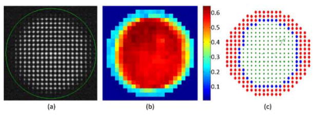
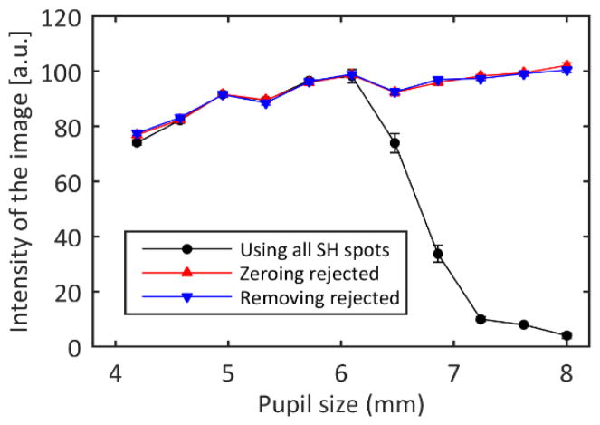
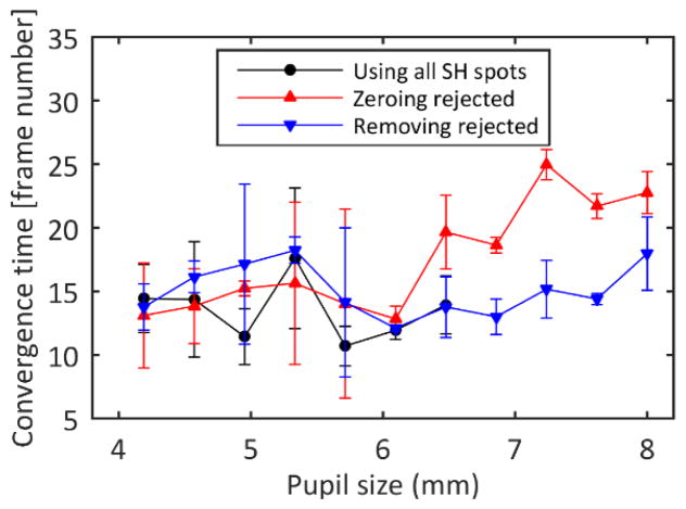
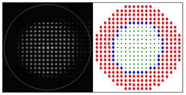
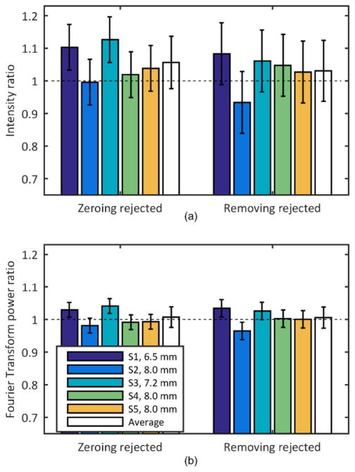
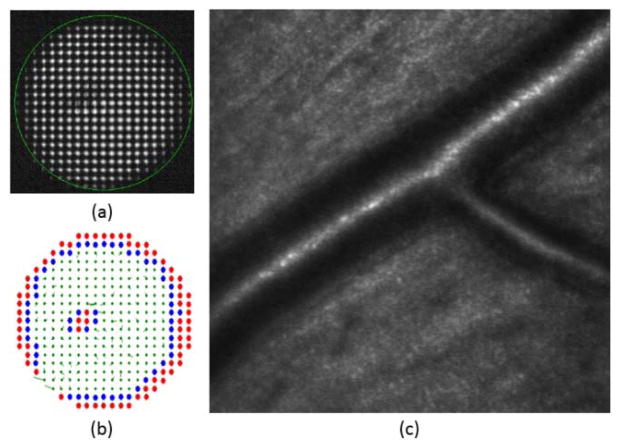
Retinal imaging with an adaptive optics (AO) system usually requires that the eye be centered and stable relative to the exit pupil of the system. Aberrations are then typically corrected inside a fixed circular pupil. This approach can be restrictive when imaging some subjects, since the pupil may not be round and maintaining a stable head position can be difficult. In this paper, we present an automatic algorithm that relaxes these constraints. An image quality metric is computed for each spot of the Shack-Hartmann image to detect the pupil and its boundary, and the control algorithm is applied only to regions within the subject's pupil. Images on a model eye as well as for five subjects were obtained to show that a system exit pupil larger than the subject's eye pupil could be used for AO retinal imaging without a reduction in image quality. This algorithm automates the task of selecting pupil size. It also may relax constraints on centering the subject's pupil and on the shape of the pupil.


Figures

Fig. 1
Fig. 1
(a) CCD image of the Shack Hartmann wavefront sensor. The green circle indicates the area monitored by the Adaptive Optics control algorithm. (b) Metric value of all the spots of the image. (c) Lenslets with metric above 0.5 were accepted (in green), and those with metric below 0.5 (in red) or in the pupil boundary (in blue) were marked for rejection. In the last image the local slope errors for accepted lenslets are drawn as vectors.
Fig. 2
Fig. 2
Final intensity of the model eye images as a function of the control pupil size for each of the control algorithms. If all the SH spots are used to control the AO loop, the best practice is to choose a pupil slightly smaller than the eye pupil since the misinformation from areas outside the eye pupil decreases the image quality. When the rejected spots are excluded, the image quality is maintained, even when controlling pupil sizes larger than the eye’s pupil, which was 6 mm. The error bars represent the standard deviation of three repeated measurements.
Fig. 3
Fig. 3
Convergence time estimated as the time elapsed between the initiation of the Adaptive Optics algorithm and the moment when the intensity on the images is 90% of the final intensity. The error bars represent the standard deviation of three repeated measurements.
Fig. 4
Fig. 4
Raw SH image (left) with a circle indicating the area of the system pupil subtended by the AO system and processed image (right) where the rejected lenslets are marked in red and the lenslets identified as pupil boundary are marked in blue. For the accepted lenslets (green), the residual slopes are plotted as vectors. Changes in pupil position, pupil size and blinks were detected in real time (see Visualization 1).
Fig. 5
Fig. 5
(a) Intensity and (b) frequency content change in the images when controlling a pupil larger than the subject’s pupil and rejecting lenslets by either zeroing their slopes (Zeroing rejected, left) or removing them from the influence matrix (Removing rejected, right). The condition where the pupil size is restricted to the subject’s pupil is used as reference. The error bars represent the standard deviation of three repeated measurements.
Fig. 6
Fig. 6
Example of the automatic pupil detection algorithm in a 6-mm diameter pupil diabetic patient with a localized posterior subcapsular cataract. (a) SH image (b) depending on its metric rejected spots are marked in red, boundary spots in blue, accepted lenslets with its local slope are marked in green (c) retinal imaging showing artery walls.

Similar articles

Cited by

References

    1. Liang J, Williams DR, Miller DT. Supernormal vision and high-resolution retinal imaging through adaptive optics. J Opt Soc Am A Opt Image Sci Vis. 1997;14:2884–2892. - PubMed
    1. Roorda A, Romero-Borja F, Donnelly W, III, Queener H, Hebert T, Campbell M. Adaptive optics scanning laser ophthalmoscopy. Opt Express. 2002;10:405–412. - PubMed
    1. Hermann B, Fernández EJ, Unterhuber A, Sattmann H, Fercher AF, Drexler W, Prieto PM, Artal P. Adaptive-optics ultrahigh-resolution optical coherence tomography. Opt Lett. 2004;29:2142–2144. - PubMed
    1. Zhang Y, Rha J, Jonnal R, Miller D. Adaptive optics parallel spectral domain optical coherence tomography for imaging the living retina. Opt Express. 2005;13:4792–4811. - PubMed
    1. Niu S, Shen J, Liang C, Zhang Y, Li B. High-resolution retinal imaging with micro adaptive optics system. Appl Opt. 2011;50:4365–4375. - PubMed

LinkOut - more resources