

Three-Axis Ground Reaction Force Distribution during Straight Walking
- PMID: 29064385
- PMCID: PMC5677223
- DOI: 10.3390/s17102431
Three-Axis Ground Reaction Force Distribution during Straight Walking
Abstract
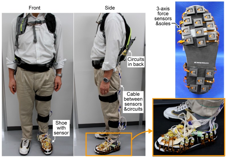
We measured the three-axis ground reaction force (GRF) distribution during straight walking. Small three-axis force sensors composed of rubber and sensor chips were fabricated and calibrated. After sensor calibration, 16 force sensors were attached to the left shoe. The three-axis force distribution during straight walking was measured, and the local features of the three-axis force under the sole of the shoe were analyzed. The heel area played a role in receiving the braking force, the base area of the fourth and fifth toes applied little vertical or shear force, the base area of the second and third toes generated a portion of the propulsive force and received a large vertical force, and the base area of the big toe helped move the body's center of mass to the other foot. The results demonstrate that measuring the three-axis GRF distribution is useful for a detailed analysis of bipedal locomotion.
Keywords: 3-axis force sensor; bipedal locomotion; force distribution; gait; ground reaction force (GRF); micro electro mechanical systems (MEMS); shoe; walk.
Conflict of interest statement
The authors declare no conflict of interest.
Figures


Similar articles
-
MEMS-Based Micro Sensors for Measuring the Tiny Forces Acting on Insects.Sensors (Basel). 2022 Oct 20;22(20):8018. doi: 10.3390/s22208018. Sensors (Basel). 2022. PMID: 36298366 Free PMC article. Review.
-
Comparing the Ground Reaction Forces, Toe Clearances, and Stride Lengths of Young and Older Adults Using a Novel Shoe Sensor System.Sensors (Basel). 2024 Oct 26;24(21):6871. doi: 10.3390/s24216871. Sensors (Basel). 2024. PMID: 39517766 Free PMC article.
-
Shear cushions reduce the impact loading rate during walking and running.Sports Biomech. 2013 Nov;12(4):334-42. doi: 10.1080/14763141.2013.841983. Sports Biomech. 2013. PMID: 24466646
-
Dynamically adjustable foot-ground contact model to estimate ground reaction force during walking and running.Gait Posture. 2016 Mar;45:62-8. doi: 10.1016/j.gaitpost.2016.01.005. Epub 2016 Jan 19. Gait Posture. 2016. PMID: 26979885
-
Shoe-Insole Technology for Injury Prevention in Walking.Sensors (Basel). 2018 May 8;18(5):1468. doi: 10.3390/s18051468. Sensors (Basel). 2018. PMID: 29738486 Free PMC article. Review.
Cited by
-
NordicWalking Performance Analysis with an Integrated Monitoring System.Sensors (Basel). 2018 May 10;18(5):1505. doi: 10.3390/s18051505. Sensors (Basel). 2018. PMID: 29748507 Free PMC article.
-
MEMS-Based Micro Sensors for Measuring the Tiny Forces Acting on Insects.Sensors (Basel). 2022 Oct 20;22(20):8018. doi: 10.3390/s22208018. Sensors (Basel). 2022. PMID: 36298366 Free PMC article. Review.
References
-
- Elftman H. A Cinematic Study of the Distribution of Pressure in the Human Foot. Anat. Rec. 1934;59:481–491. doi: 10.1002/ar.1090590409. - DOI
MeSH terms
LinkOut - more resources
Full Text Sources
Other Literature Sources
