. 2017 Oct 31;7(1):14447.
doi: 10.1038/s41598-017-15000-9.

Fault-Tolerant Control of ANPC Three-Level Inverter Based on Order-Reduction Optimal Control Strategy under Multi-Device Open-Circuit Fault

Affiliations

Fault-Tolerant Control of ANPC Three-Level Inverter Based on Order-Reduction Optimal Control Strategy under Multi-Device Open-Circuit Fault

Shi-Zhou Xu et al. Sci Rep. .

Abstract

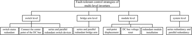
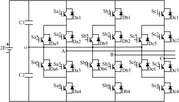
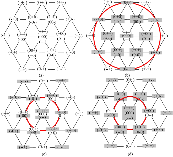
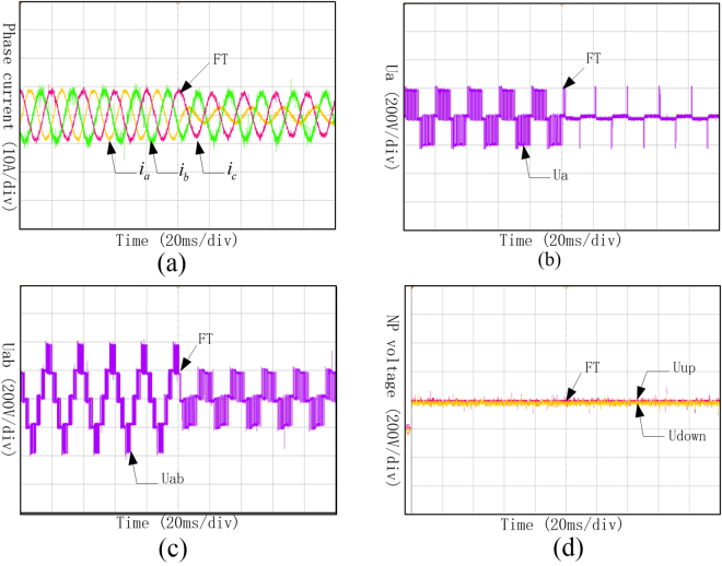
The multi-device open-circuit fault is a common fault of ANPC (Active Neutral-Point Clamped) three-level inverter and effect the operation stability of the whole system. To improve the operation stability, this paper summarized the main solutions currently firstly and analyzed all the possible states of multi-device open-circuit fault. Secondly, an order-reduction optimal control strategy was proposed under multi-device open-circuit fault to realize fault-tolerant control based on the topology and control requirement of ANPC three-level inverter and operation stability. This control strategy can solve the faults with different operation states, and can works in order-reduction state under specific open-circuit faults with specific combined devices, which sacrifices the control quality to obtain the stability priority control. Finally, the simulation and experiment proved the effectiveness of the proposed strategy.


Conflict of interest statement

The authors declare that they have no competing interests.

Figures

Figure 1
Figure 1
Categories of fault-tolerant control methods for multi-level inverters.
Figure 2
Figure 2
Flow chart of order-reduction optimal control strategy.
Figure 3
Figure 3
Topology of ANPC three-level inverter.
Figure 4
Figure 4
Current flow paths under multi-device open-circuit faults in 3-L ANPC inverter. (a) Sa5 and Sa6 in open-circuit state; (b) Sa5/Da5 and Sa6/Da6 in open-circuit state; (c) Sa1/Da1, Sa3/Da3, Sa4/Da4 and Sa6/Da6 in open circuit state; (d) Sa1/Da1, Da2, Da3, Sa4/Da4, Sa5 and Sa6 in open-circuit state.
Figure 5
Figure 5
Voltage vector diagram of 3L-ANPC inverter under multi-device open-circuit fault.
Figure 6
Figure 6
Voltage vector diagram of 3L-ANPC inverter using lower dc-link capacitor for fault tolerant operation.
Figure 7
Figure 7
Phase current, phase voltage, line voltage and neutral-point voltage under Sa1 and Sa4 open-circuit fault. (a) Three-phase currents under Sa1 and Sa4 open-circuit fault; (b) Phase voltage of phase A under Sa1 and Sa4 open-circuit fault; (c) Line voltage between phase A and B under Sa1 and Sa4 open-circuit fault; (d) Neutral-point voltage under Sa1 and Sa4 open-circuit fault.
Figure 8
Figure 8
Phase current, phase voltage, line voltage and neutral-point voltage under Sa1 and Sa4 open-circuit fault with fault-tolerant control. (a) Three-phase currents under Sa1 and Sa4 open-circuit fault with fault-tolerant control; (b) Phase voltage of phase A under Sa1 and Sa4 open-circuit fault with fault-tolerant control; (c) Line voltage between phase A and B under Sa1 and Sa4 open-circuit fault with fault-tolerant control; (d) Neutral-point voltage under Sa1 and Sa4 open-circuit fault with fault-tolerant control.
Figure 9
Figure 9
Phase current, phase voltage, line voltage and neutral-point voltage under Sa1 and Sa5 open-circuit fault. (a) Three-phase currents under Sa1 and Sa5 open-circuit fault; (b) Phase voltage of phase A under Sa1 and Sa5 open-circuit fault; (c) Line voltage between phase A and B under Sa1 and Sa5 open-circuit fault; (d) Neutral-point voltage under Sa1 and Sa5 open-circuit fault.
Figure 10
Figure 10
Phase current, phase voltage, line voltage and neutral-point voltage under Sa1 and Sa5 open-circuit fault with fault-tolerant control. (a) Three-phase currents under Sa1 and Sa5 open-circuit fault with fault-tolerant control; (b) Phase voltage of phase A under Sa1 and Sa5 open-circuit fault with fault-tolerant control; (c) Line voltage between phase A and B under Sa1 and Sa5 open-circuit fault with fault-tolerant control; (d) Neutral-point voltage under Sa1 and Sa5 open-circuit fault with fault-tolerant control.
Figure 11
Figure 11
Phase current, phase voltage, line voltage and neutral-point voltage under Sa5 and Sa6 open-circuit fault with fault-tolerant control. (a) Three-phase currents under Sa5 and Sa6 open-circuit fault with fault-tolerant control; (b) Phase voltage of phase A under Sa5 and Sa6 open-circuit fault with fault-tolerant control; (c) Line voltage between phase A and B under Sa5 and Sa6 open-circuit fault with fault-tolerant control; (d) Neutral-point voltage under Sa5 and Sa6 open-circuit fault with fault-tolerant control.
Figure 12
Figure 12
The experiment platform. (a) The front of the experiment platform; (b) The front of the experiment platform.
Figure 13
Figure 13
Waveforms of phase current, phase voltage, line voltage and neutral-point voltage under Sa1 and Sa4 open-circuit fault. (a) Three-phase currents under Sa1 and Sa4 open-circuit fault; (b) Phase voltage of phase A under Sa1 and Sa4 open-circuit fault; (c) Line voltage between phase A and B under Sa1 and Sa4 open-circuit fault; (d) Neutral-point voltage under Sa1 and Sa4 open-circuit fault.
Figure 14
Figure 14
Waveforms of phase current, phase voltage, line voltage and neutral-point voltage under Sa1 and Sa4 open-circuit fault with fault-tolerant control. (a) Three-phase currents under Sa1 and Sa4 open-circuit fault with fault-tolerant control; (b) Phase voltage of phase A under Sa1 and Sa4 open-circuit fault with fault-tolerant control; (c) Line voltage between phase A and B under Sa1 and Sa4 open-circuit fault with fault-tolerant; (d) Neutral-point voltage under Sa1 and Sa4 open-circuit fault with fault-tolerant control.
Figure 15
Figure 15
Waveforms of phase current, phase voltage, line voltage and neutral-point voltage under Sa1 and Sa5 open-circuit fault. (a) Three-phase currents under Sa1 and Sa5 open-circuit fault; (b) Phase voltage of phase A under Sa1 and Sa5 open-circuit fault; (c) Line voltage between phase A and B under Sa1 and Sa5 open-circuit fault; (d) Neutral-point voltage under Sa1 and Sa5 open-circuit fault.
Figure 16
Figure 16
Waveforms of phase current, phase voltage, line voltage and neutral-point voltage under Sa1 and Sa5 open-circuit fault with fault-tolerant control. (a) Three-phase currents under Sa1 and Sa5 open-circuit fault with fault-tolerant control; (b) Phase voltage of phase A under Sa1 and Sa5 open-circuit fault with fault-tolerant control; (c) Line voltage between phase A and B under Sa1 and Sa5 open-circuit fault with fault-tolerant; (d) Neutral-point voltage under Sa1 and Sa5 open-circuit fault with fault-tolerant control.
Figure 17
Figure 17
Waveforms of phase current, phase voltage, line voltage and neutral-point voltage under Sa5 and Sa6 open-circuit fault. (a) Three-phase currents under Sa5 and Sa6 open-circuit fault; (b) Phase voltage of phase A under Sa5 and Sa6 open-circuit fault; (c) Line voltage between phase A and B under Sa5 and Sa6 open-circuit fault; (d) Neutral-point voltage under Sa5 and Sa6 open-circuit fault.

References

    1. Park, J. J., Kim, T. J. & Hyun, D. S. Study of neutral point potential variation for three-level NPC inverter under fault condition. Industrial Electronics, 2008. IECON 2008. Conference of IEEE, 983–988 (2008).
    1. Choi UM, Lee KB, Blaabjerg F. Diagnosis and tolerant strategy of an open-switch fault for t-type three-level inverter systems. IEEE Transactions on Industry Applications. 2014;50(1):495–508. doi: 10.1109/TIA.2013.2269531. - DOI
    1. Lezana P, Pou J, Meynard TA, et al. Survey on fault operation on multilevel inverters[J] IEEE Transactions on Industrial Electronics. 2010;57(7):2207–2218. doi: 10.1109/TIE.2009.2032194. - DOI
    1. Li S, Xu L. Strategies of fault tolerant operation for three-level pwm inverters. IEEE Transactions on Power Electronics. 2006;21(4):933–940. doi: 10.1109/TPEL.2006.876867. - DOI
    1. Mohammadpour A, Sadeghi S, Parsa L. A generalized fault-tolerant control strategy for five-phase pm motor drives considering star, pentagon, and pentacle connections of stator windings. IEEE Transactions on Industrial Electronics. 2013;61(1):63–75. doi: 10.1109/TIE.2013.2247011. - DOI

Publication types

LinkOut - more resources