

Review
doi: 10.1161/JAHA.117.007353.
Use of Cardiac Computerized Tomography to Predict Neo-Left Ventricular Outflow Tract Obstruction Before Transcatheter Mitral Valve Replacement
Affiliations
- PMID: 29102981
- PMCID: PMC5721795
- DOI: 10.1161/JAHA.117.007353
Item in Clipboard
Review
Use of Cardiac Computerized Tomography to Predict Neo-Left Ventricular Outflow Tract Obstruction Before Transcatheter Mitral Valve Replacement
J Am Heart Assoc.
.
No abstract available
Keywords: Cardiac CT; Left ventricular outflow tract; Mitral valve; Transcatheter mitral valve replacement.
Figures
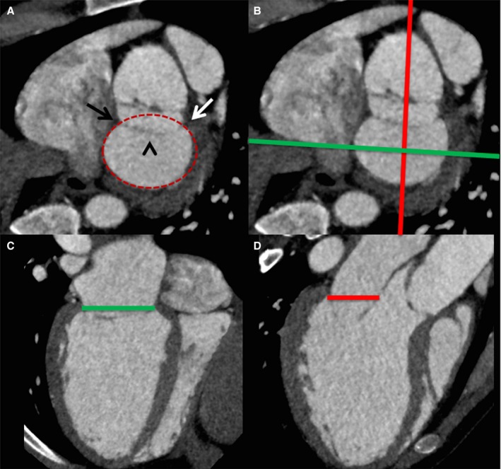
Performing mitral annular measurements and defining the annular plane on cardiac computerized tomography. A, Short‐axis view of the mitral annular region demonstrates the medial (black arrow) and lateral (white arrow) fibrous trigones, the anterior mitral valve leaflet (arrowhead), with delineation of the annular perimeter (red oval). The green and red lines in (B) demonstrate the orientation of the commissural view in (C) and long‐axis view in (D), with delineation of the mitral annular plane.
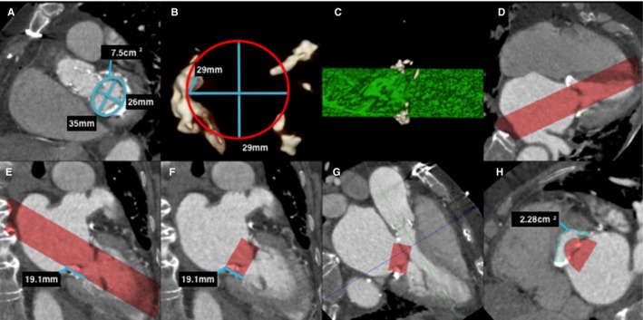
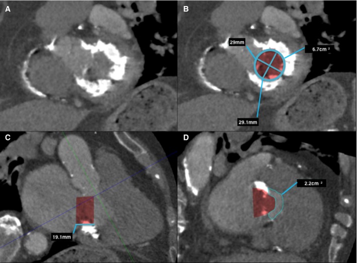
Predicting neo–left ventricular outflow tract (LVOT ) area in a native mitral valve on postcontrast cardiac computerized tomography (CT ). A, Left ventricle short‐axis multiplanar reformat (MPR ) at the level of the mitral annulus demonstrates mitral annulus measurements. Note the mild mitral annular calcification. B, A 3‐dimensional (3D) circular volume‐rendered segmentation (red circle) is performed at the corresponding level of the mitral annulus with the dimensions of the proposed prosthetic valve (in this case a 29‐mm Edwards SAPIEN XT valve). C, This creates a 3D segmented cylindrical volume (green cylinder), viewed here in profile. D, Once segmented, the segmented 3D volume can be projected onto the CT image data, as demonstrated on this 4‐chamber MPR (red volume). E, The proposed prosthetic valve height is then measured (line) and segmented (F) as demonstrated on these 2‐chamber MPR s. G, A 3‐chamber MPR can determine the level of the minimal neo‐LVOT (blue line), and planimetry of the neo‐LVOT can be performed in an orthogonal plane (H).
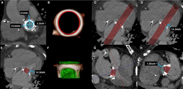
Predicting neo–left ventricular outflow tract (LVOT ) area in a prosthetic mitral valve on postcontrast cardiac computerized tomography (CT ) using 30 mL iodinated contrast. A, Left ventricle short‐axis multiplanar reformat (MPR ) at the level of the mechanical mitral valve demonstrates mitral valve prosthetic measurements. B, A 3‐dimensional (3D) volume segmentation (red circle) is performed of the internal surface of the prosthetic valve at the corresponding level of the mitral annulus with the dimensions of the proposed prosthetic valve (in this case a 23‐mm Edwards SAPIEN XT valve). C, Four‐chamber MPR demonstrates the resulting segmented volume (red volume). D, The valve height (line) is then segmented (E), and 4‐chamber MPR shows the proposed valve prosthesis. F, A 3D segmented volume‐rendered image demonstrates the prosthetic valve volume (green cylinder) in profile inside the existing prosthesis. G, Three‐chamber MPR demonstrates the level of the neo‐LVOT (blue line), with planimetry of the neo‐LVOT performed in an orthogonal plane (H).
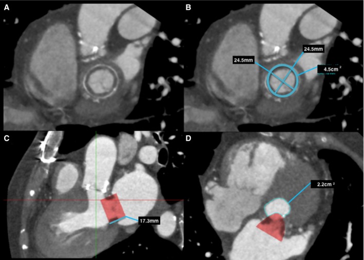
Predicting neo–left ventricular outflow tract (LVOT ) area in a bioprosthetic mitral valve on postcontrast cardiac computerized tomography (CT ). A, Left ventricle short‐axis multiplanar reformat (MPR ) at the level of the bioprosthetic mitral valve, with annotated measurements (B). C, Three‐chamber MPR demonstrates the proposed valve prosthesis, in this case a 26‐mm Edwards SAPIEN XT valve. Planimetry of the neo‐LVOT (C, red line), with planimetry of the neo‐LVOT performed in an orthogonal plane (D).
Predicting neo–left ventricular outflow tract (LVOT ) area in a native mitral valve with severe mitral annular calcification on postcontrast cardiac computerized tomography (CT ) using 30 mL iodinated contrast. A, Left ventricle short‐axis multiplanar reformat (MPR ) at the level of the mitral annulus with severe mitral annular calcification, with (B) mitral annular measurements and segmented valve area. Three‐chamber MPR (C) demonstrates the proposed valve prosthesis, in this case a 29‐mm Edwards SAPIEN XT valve. Planimetry of the neo‐LVOT (C, blue line), with planimetry of the neo‐LVOT performed in an orthogonal plane (D).
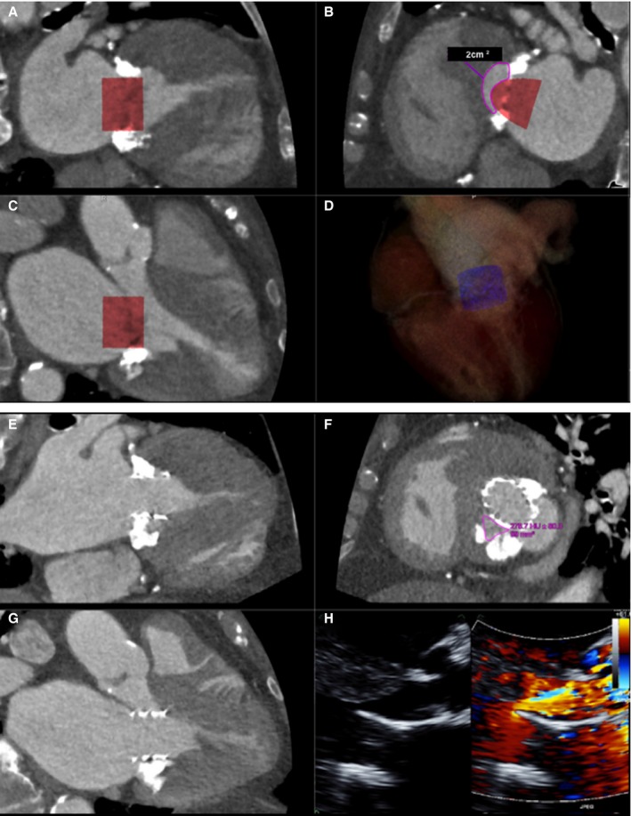
A through D, ECG gated, contrast‐enhanced cardiac computerized tomography (CT ) images at end systole showing (A) commissural and (B) 3‐chamber views with a simulated cylindrical device (29 mm) oriented perpendicularly to the annular plane. One third of the cylinder volume is projected to remain above the plane in the commissural view. The neo–left ventricular outflow tract (LVOT ) formed by the septal myocardium and the device is shown in (C) with cross‐sectional area of 2.0 cm2, indicating risk for LVOT obstruction. D, Three‐dimensional segmented rendering of the cylinder within the left ventricle. E through H, Contrast‐enhanced cardiac CT at end systole showing a deployed 26‐mm Edwards SAPIEN 3 transcatheter heart valve in the mitral position, which was placed more apically than on the 3‐dimensional (3D) simulation. Commissural (E), 3‐chamber (F), and neo‐LVOT (G) views demonstrate end‐systolic area of 0.99 cm2. A transthoracic echocardiogram (H) showed flow acceleration across the LVOT with evidence of dynamic obstruction (peak gradient measured at 58 mm Hg and mean gradient at 26 mm Hg). Despite this, the procedure was clinically successful, as the patient experienced significant improvement in her functional status. Mean gradients across the mitral valve decreased from 11 mm Hg (at a heart rate of 70 beats/min) to 6 mm Hg (at a heart rate of 80 beats/min).
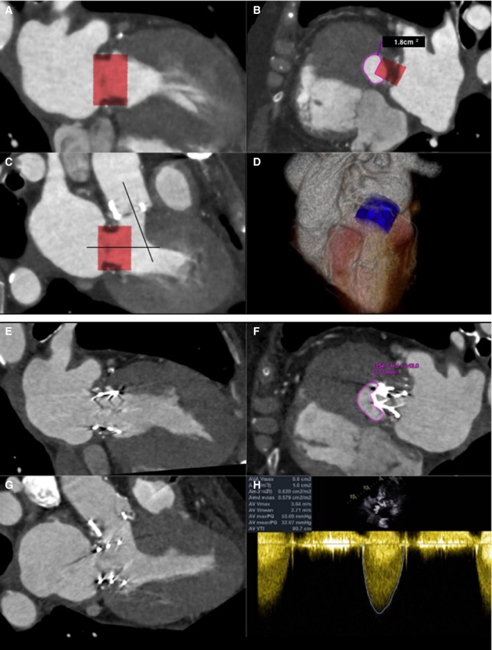
A through D, ECG gated, contrast‐enhanced cardiac computerized tomographic image (CT ) at end systole showing (A) commissural and (B) 3‐chamber views with a simulated Edwards SAPIEN XT valve (26 mm) oriented perpendicularly to the annular plane of a bioprosthetic St. Jude valve (27 mm). Note the acute aortomitral angle. One third of the cylinder volume is projected to remain above the annular plane. The neo–left ventricular outflow tract (LVOT ) formed by the septal myocardium and the device is shown (C) with cross‐sectional area of 1.8 cm2, indicating high risk for LVOT obstruction. D, Three‐dimensional (3D) rendering of the cylinder within the left ventricle. E through H, Contrast‐enhanced cardiac CT at end systole showing an Edwards SAPIEN XT transcatheter heart valve (26 mm) in the mitral position. Commissural (E), 3‐chamber (F), and neo‐LVOT (G) views demonstrate end‐systolic area of 1.7 cm2. A transthoracic echocardiogram (H) showed combined peak and mean gradients across the LVOT /bioprosthetic aortic valve of 53 and 32 mm Hg. Pre–transcatheter mitral valve replacement (TMVR ) peak and mean gradients across the aortic valve were 37 and 13 mm Hg, respectively. The procedure, performed for early bioprosthetic valve failure and severe mitral regurgitation (MR ), was clinically successful. Intraoperative transesophageal echocardiogram showed trivial MR after the deployment of the TMVR , which translated into improved symptoms.
References
-
- Nishimura RA, Vahanian A, Eleid MF, Mack MJ. Mitral valve disease—current management and future challenges. Lancet. 2016;387:1324–1334. - PubMed
-
- Feldman T, Kar S, Elmariah S, Smart SC, Trento A, Siegel RJ, Apruzzese P, Fail P, Rinaldi MJ, Smalling RW, Hermiller JB, Heimansohn D, Gray WA, Grayburn PA, Mack MJ, Lim DS, Ailawadi G, Herrmann HC, Acker MA, Silvestry FE, Foster E, Wang A, Glower DD, Mauri L; EVEREST II Investigators . Randomized comparison of percutaneous repair and surgery for mitral regurgitation: 5‐year results of EVEREST II. J Am Coll Cardiol. 2015;66:2844–2854. - PubMed
-
- Ruel M, Kulik A, Rubens FD, Bédard P, Masters RG, Pipe AL, Mesana TG. Late incidence and determinants of reoperation in patients with prosthetic heart valves. Eur J Cardiothorac Surg. 2004;25:364–370. - PubMed
-
- Paradis JM, Del Trigo M, Puri R, Rodés‐Cabau J. Transcatheter valve‐in‐valve and valve‐in‐ring for treating aortic and mitral surgical prosthetic dysfunction. J Am Coll Cardiol. 2015;66:2019–2037. - PubMed
-
- Muller DWM, Farivar RS, Jansz P, Bae R, Walters D, Clarke A, Grayburn PA, Stoler RC, Dahle G, Rein KA, Shaw M, Scalia GM, Guerrero M, Pearson P, Kapadia S, Gillinov M, Pichard A, Corso P, Popma J, Chuang M, Blanke P, Leipsic J, Sorajja P; Tendyne Global Feasibility Trial Investigators . Transcatheter mitral valve replacement for patients with symptomatic mitral regurgitation: a global feasibility trial. J Am Coll Cardiol. 2017;69:381–391. - PubMed
Publication types
MeSH terms
LinkOut - more resources
Full Text Sources
Other Literature Sources
Medical
