. 2018 Feb;25(2):10.1111/micc.12429.
doi: 10.1111/micc.12429.

Biophysical properties of microvascular endothelium: Requirements for initiating and conducting electrical signals

Affiliations

Biophysical properties of microvascular endothelium: Requirements for initiating and conducting electrical signals

Adam Kapela et al. Microcirculation. 2018 Feb.

Abstract

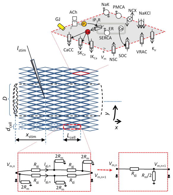
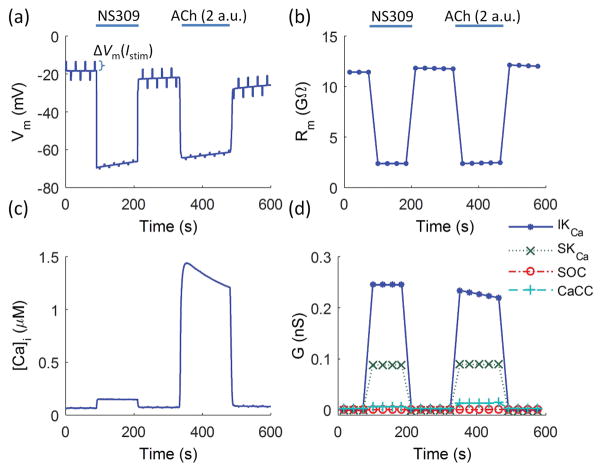
Objective: Electrical signaling along the endothelium underlies spreading vasodilation and blood flow control. We use mathematical modeling to determine the electrical properties of the endothelium and gain insight into the biophysical determinants of electrical conduction.

Methods: Electrical conduction data along endothelial tubes (40 μm wide, 2.5 mm long) isolated from mouse skeletal muscle resistance arteries were analyzed using cable equations and a multicellular computational model.

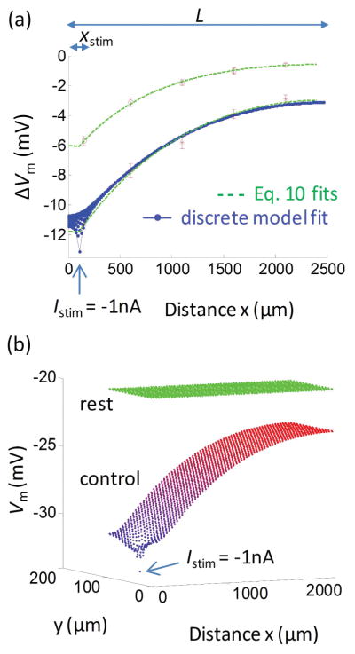
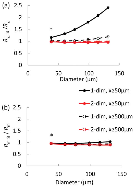
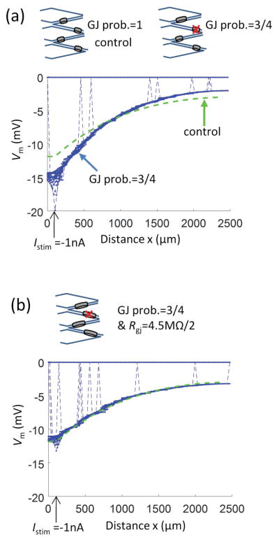
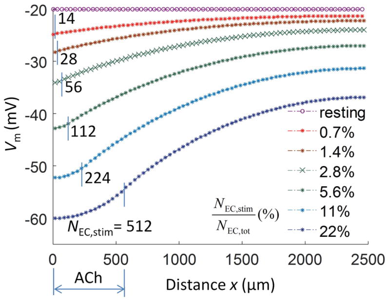
Results: Responses to intracellular current injection attenuate with an axial length constant (λ) of 1.2-1.4 mm. Data were fitted to estimate the axial (ra ; 10.7 MΩ/mm) and membrane (rm ; 14.5 MΩ∙mm) resistivities, EC membrane resistance (Rm ; 12 GΩ), and EC-EC coupling resistance (Rgj ; 4.5 MΩ) and predict that stimulation of ≥30 neighboring ECs is required to elicit 1 mV of hyperpolarization at distance = 2.5 mm. Opening Ca2+ -activated K+ channels (KCa ) along the endothelium reduced λ by up to 55%.

Conclusions: High Rm makes the endothelium sensitive to electrical stimuli and able to conduct these signals effectively. Whereas the activation of a group of ECs is required to initiate physiologically relevant hyperpolarization, this requirement is increased by myoendothelial coupling and KCa activation along the endothelium inhibits conduction by dissipating electrical signals.

Keywords: endothelium; membrane potential; membrane resistance; modeling; spreading vasodilation.


Conflict of interest statement

Competing interests

The authors declare that there are no conflicts of interest.

Figures

Figure 1
Figure 1
Discrete multicellular model of endothelial tube. Idealized diamond-shaped ECs, each with length = 35 μm (Lcell), width = 8.6 μm (dcell), and thickness d, are arranged into a cylinder (dashed lines) with Ncircum (= 14) cells encompassing the circumferential direction (y) and 71 cells encompassing the axial direction (x). Under control conditions, each EC is coupled to its four immediate neighbors through gap junctions. The total number of ECs in the discrete model of an endothelial tube of length L = 2.5 mm and diameter D = 38 μm is 1988. Each EC is modeled as described in Silva et al. and contains: store-operated Ca2+channels (SOC); nonselective cation channels (NSC); volume regulated anion channels (VRAC); Ca2+-activated Cl channels (CaCC); small- and intermediate-conductance Ca2+-activated K+ channels (SKCa and IKCa); Na+-K+-ATPase (NaK); plasma membrane Ca2+-ATPase (PMCA); Na+/Ca2+ exchanger (NCX); Na+/K+/Cl cotransporter (NaKCl); sarcoplasmic endoplasmic reticulum Ca2+-ATPase (SERCA); and IP3 receptors (IP3R). The electrical equivalent diagram of a rectangular region (dashed red line), which incorporates four halves of ECs and four gap junctions is shown (bottom right). Each EC has a total membrane resistance Rm, each EC-EC coupling has resistance Rgj, and there are Ncircum such rectangular regions in the circumferential direction. The effective membrane and axial resistivities of the endothelial tube can be derived from Ncircum parallel units having membrane resistance of Rm/2 and axial resistance of Rgj over distance Lcell.
Figure 2
Figure 2
(a) Fittings of the cable and discrete models to experimental data. Data were taken from experiments under control conditions (red stars) and following NS309 induced opening of SKCa/IKCa (red circles), corresponding to Istim = −1 nA of current injection. Fitting short cable equation (Eq. 10) to the control and NS309 data yields λ = 1.16±0.12 mm and 0.78±0.05 mm, respectively (dashed green lines). Fitting of the discrete endothelial tube model gives a family of ΔVm profiles (blue dotted lines). The most negative profile corresponds to the ECs located at the circumferential position that incorporates the stimulus point. Only this profile from the discrete model was used to fit the data. The remaining profiles predict Vm responses at different positions in the circumferential direction; all merge to the same profile within ~400 μm distance from the stimulus. (b) Vm profiles in axial and circumferential directions predicted in the discrete model fitting the control data in (a). Under resting conditions, all 1988 cells have Vm = −20 mV (green dots). Each dot represents Vm in individual EC. Injection of Istim = −1 nA into a single EC (at site indicated by arrow) creates strong Vm hyperpolarization and gradients in both circumferential (y) and axial (x) dimensions from the local site of intracellular current injection. In these simulations, values for EC membrane resistance and coupling resistance were Rm = 11.9 GΩ and Rgj = 4.5 MΩ. At distances xxstim> 400 μm, Vm profile is effectively isopotential in the circumferential direction, and the stimulus current spreads only in the axial direction.
Figure 3
Figure 3
(a–b) Estimations of the error for coupling resistance (a) and membrane resistance (b) as a function of endothelial tube circumference for different fitting schema. The discrete model with known Rm (= 11.9 GΩ) and Rgj (= 4.5 MΩ) (Fig. 1a) and control diameter Dcontrol = 38 μm was expanded in the circumferential direction to simulate hypothetical endothelial tubes with increasing diameters (D). Model predictions of ΔVm in response to current injection at xstim were used to simulate Vm measurements along an endothelial tube. The simulated ΔVm were fitted with one- and two-dimensional cable equations (Eqs. 10 and 16) to estimate Rgj,fit (a) and Rm,fit (b). The fittings were performed with ΔVm at xxstim= 50, 500, 1000, 1500, and 2000 μm (in the axial direction) (diamond and square symbols), and ΔVm only at xxstim≥ 500 μm (triangles and crosses). Fitting the two-dimensional equation recovers correctly Rgj and Rm (Rgj,fit/Rgj λ 1 and Rm,fit/Rm λ 1) for all diameters and data points (a, b squares and crosses). On the other hand, the one-dimensional equation overestimates Rgj (Rgj,fit/Rgj≫ 1) when applied to data with the 50 μm point from vessels > 50 μm in diameter (a, diamond symbols).
Figure 4
Figure 4
Impact of reduced gap junctional coupling on electrical conduction along resistance artery endothelium. (a) Representative simulation where the probability of gap junction connection between the two neighbor ECs is reduced from 100% (the control model) to 75%. (b) The resistance of individual EC-EC connections is reduced by half from the control Rgj of 4.5 MΩ in (a). In both panels the same hyperpolarizing current Istim = −1 nA was injected into a single EC at xstim = 100 μm. The one-dimensional short cable (Eq. 10) fit of the control profile from Figure 2a is also shown for reference to control conditions (dashed green line).
Figure 5
Figure 5
Impact of SKCa/IKCa activation on endothelial membrane potential and membrane resistance predicted by the isolated EC model. (a) Predicted Vm during direct maximum (100%) opening of SKCa/IKCa (NS309) followed by application of ACh (2 a.u.). To determine Rm at individual time points, current pulses were applied periodically (±0.4 pA for 2 s every 30 s), whereby the ratio of the resulting ΔVm to the injected current corresponded to Rm. (b) Predicted changes in Rm (defined as ΔVm/Istim) show ~80% drop during direct SKCa/IKCa opening with NS309 and during indirect SKCa/IKCa opening with ACh (from Rm = 11.5 GΩ to Rm = 2.4 GΩ). [Ca2+] transient and corresponding changes in channel conductance (G) during the stimulations are shown in (c) and (d).
Figure 6
Figure 6
Initiation and conduction of hyperpolarization reflects how many endothelial cells are stimulated. In the discrete multicellular model, profiles of spreading hyperpolarization (Vm) in the axial direction (x) are shown for different number of ECs stimulated (NEC,stim) with ACh. The total number of ECs NEC,tot = 1988. In each profile (stars), ECs at the site of stimulation were exposed to saturating [ACh] (3 a.u.). The resting Vm profile is shown for reference (circles). Approximately 56 ECs require stimulation to evoke a conducted response (green crosses) similar to injecting Istim = −1 nA (compare with Fig. 2a) and millivolt-level hyperpolarization is achieved at 2.5mm away from the local site with stimulation of 14 ECs (i.e. one column). The magnitude of hyperpolarization is a saturating function (Michaelis-Menten type) of NEC,stim (Eq. 24).

References

    1. Segal SS. Regulation of blood flow in the microcirculation. Microcirculation. 2005;12:33–45. - PubMed
    1. Busse R, Edwards G, Feletou M, Fleming I, Vanhoutte PM, Weston AH. EDHF: bringing the concepts together. Trends Pharmacol Sci. 2002;23:374–380. - PubMed
    1. Bagher P, Segal SS. Regulation of blood flow in the microcirculation: role of conducted vasodilation. Acta Physiol (Oxf) 2011;202:271–284. - PMC - PubMed
    1. Segal SS, Duling BR. Communication between feed arteries and microvessels in hamster striated muscle: segmental vascular responses are functionally coordinated. Circ Res. 1986;59:283–290. - PubMed
    1. Cohen KD, Berg BR, Sarelius IH. Remote arteriolar dilations in response to muscle contraction under capillaries. Am J Physiol Heart Circ Physiol. 2000;278:H1916–1923. - PubMed

Publication types

Substances