. 2017 Nov 15;7(1):15625.
doi: 10.1038/s41598-017-15506-2.

Design of Cultured Neuron Networks in vitro with Predefined Connectivity Using Asymmetric Microfluidic Channels

Affiliations

Design of Cultured Neuron Networks in vitro with Predefined Connectivity Using Asymmetric Microfluidic Channels

Arseniy Gladkov et al. Sci Rep. .

Abstract

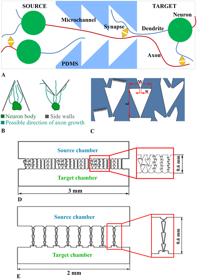
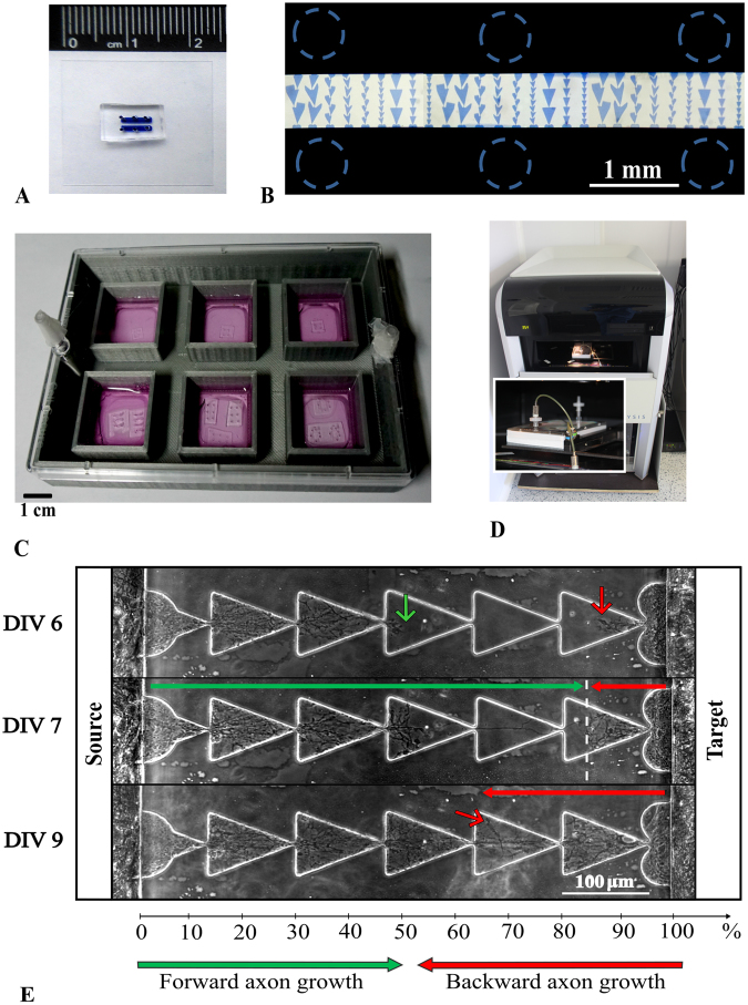
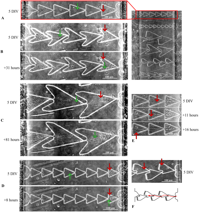
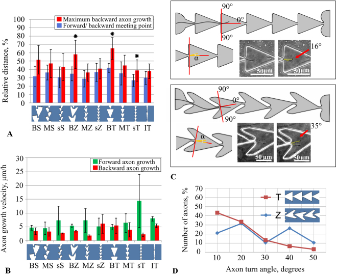
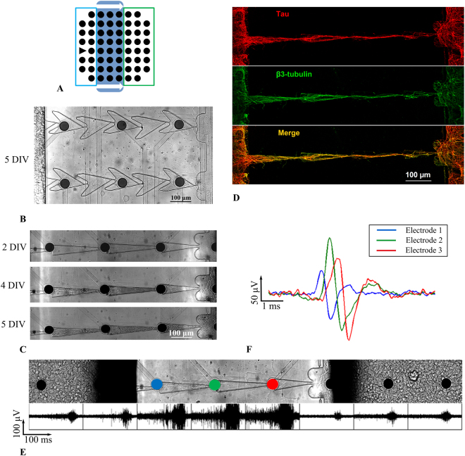
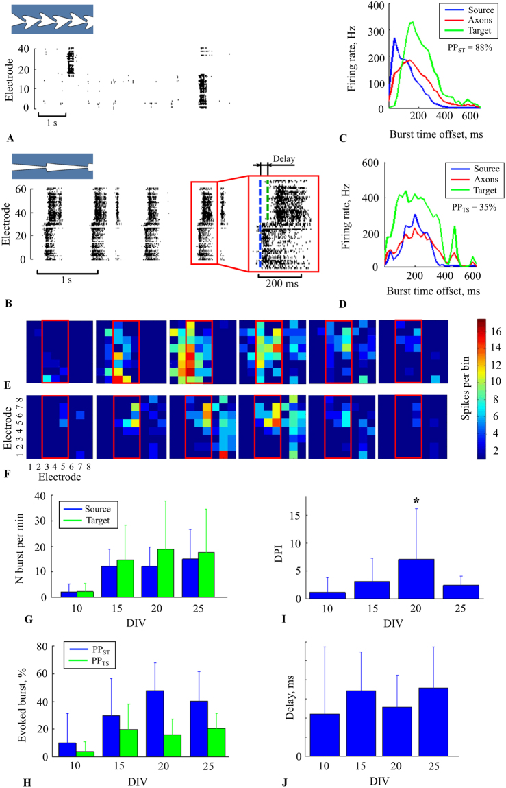
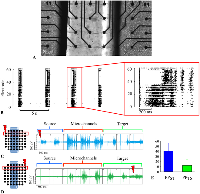
The architecture of neuron connectivity in brain networks is one of the basic mechanisms by which to organize and sustain a particular function of the brain circuitry. There are areas of the brain composed of well-organized layers of neurons connected by unidirectional synaptic connections (e.g., cortex, hippocampus). Re-engineering of the neural circuits with such a heterogeneous network structure in culture may uncover basic mechanisms of emergent information functions of these circuits. In this study, we present such a model designed with two subpopulations of primary hippocampal neurons (E18) with directed connectivity grown in a microfluidic device with asymmetric channels. We analysed and compared neurite growth in the microchannels with various shapes that promoted growth dominantly in one direction. We found an optimal geometric shape features of the microchannels in which the axons coupled two chambers with the neurons. The axons grew in the promoted direction and formed predefined connections during the first 6 days in vitro (DIV). The microfluidic devices were coupled with microelectrode arrays (MEAs) to confirm unidirectional spiking pattern propagation through the microchannels between two compartments. We found that, during culture development, the defined morphological and functional connectivity formed and was maintained for up to 25 DIV.


Conflict of interest statement

The authors declare that they have no competing interests.

Figures

Figure 1
Figure 1
Microfluidic chip with microchannels for unidirectional axon growth between two cultured networks. (A) Schematic view of neural network connectivity in the device with two chambers and microchannels. The shape of the microchannel provides axon growth from the Source to the Target chamber. (B) Schematic view of axon growth through bottlenecks (C) Shapes: “Spines”, “Triangles” and “Zig-zag”. Characteristic dimensions: Width (W) = 60–160 µm, Bottleneck width (w) = 5 µm, Height = 5 µm, Length (L) = 66, 70, 100, 200 µm. (D) Microfluidic chip with 9 variations of 3 types of microchannels. (E) Microfluidic chip with triangle shaped microchannels. Bottleneck width (w) = 7 µm, Width (W) = 60 µm, Length (L) = 200 µm.
Figure 2
Figure 2
Experimental setup to study neurite growth in microfluidic chips. (A) Two-chamber microfluidic chip (B) Photo of the chip filled with methylene blue; dashed circles marked punch holes for cell plating. Bar length 1 mm (C) A 6-well plate with microfluidic chips attached to coverslips. Bar length 1 cm. (D) The automated inverted microscope system Cell IQ (see Methods) was used to study neurite growth from the 6-well plate (see Methods). (E) Example of neurite outgrowth during development: top- DIV 6, middle- DIV 7 when axons from the Source chamber met oppositely grown axons from the Target chamber, bottom- DIV 9 when the axon grew from Target chamber alongside the neurons from the Source chamber, and both were still distinguishable (see Support Video S6).
Figure 3
Figure 3
Directional neurite growth in the various shaped microchannels. (A) Two neuronal cultures grown on microfluidic chips with asymmetric microchannels guiding the neurites from the Source chamber (left) to the Target chamber (right). The image was obtained on the 5th day in vitro (DIV). (B) “Zig-zag” shape of the microchannel composed of medium sized sections (100 µm length). Group of neurites growing dominantly in one direction (left to right, green arrow) through bottlenecks, while opposite direction growth (red arrow) was limited by “horn” traps. On the 7th DIV, the neurites from the Source chamber reached the final segment where they met the neurites grown from the Target. (Support Video S1). (C) Neurite growth in large “Zig-zag” segments (see Methods). Neurites passed 2 bottlenecks and met neurites from the Target culture on the 8th DIV. (Support Video S2). (D) Neurites in “triangle” shaped microchannels passed 8 bottlenecks and reached the final segment on the 5th DIV, while neurites from the Target chamber passed only one and remained in the last segment the whole time. (Support Video S3). (E) Neurites growing “backward” from the Target culture alongside the neurites grown from the Source. (Support Video S4). (F) Neurites in “Spine” shaped segments may grow from the Target culture into a trap (upper red arrow), while others may grow through the bottleneck alongside the boundary (lower arrow). (Support Video S5).
Figure 4
Figure 4
Neurite growth characteristics for various microchannel designs. (A) Forward/backward meeting point - the point where forward axon growth met backward growth, counting from the end of the channel (blue bars). Maximum backward neurite growth was defined as the maximum visible lengths of the processes growing from the Target chamber (red bars). The values represented the growth distance relative to microchannel length, which was 600 µm (means ± SD, n = 6 cultures, 138 microchannels). (B) Growth velocities for forward and backward directions measured within a single segment (mean ± SD, n = 6 cultures, 121 segments). (C) Angle of the neurite growth trajectory when it passed the bottleneck going to the Target chamber. (D) Distribution of the neurite outgrowth angles from “Triangle” and “Zig-zag” bottleneck types.
Figure 5
Figure 5
Bursting activity recorded on a multielectrode array combined with a microfluidic chip. (A) Schematic view of the microfluidic device mounted to the MEA. Blue box- Source chamber, green box- Target chamber, triangle- reference electrode. (B) Axons grew through the microchannels with 100-µm “Zig-zag” segments, 5 DIV. (C) Axons grew through the microchannels with narrow triangular segments up to 5 days. (D) Immunostaining image of the neuronal membrane (b3-tubulin, green) and axonal compartments (tau, red). The yellow colour on the merged image (bottom) indicates axons in the culture. (E) Electrophysiological signals recorded from the MEA electrodes. Spontaneous spiking activity consisted of 100–200 ms bursts. (F) Single spike propagation recorded from three electrodes inside the microchannel. Blue, red and green colours of the signals corresponded to the electrodes from a single microchannel.
Figure 6
Figure 6
Bursting activity propagated between two cultures through the microchannels. (A) Raster plot of spiking activity in the chip with “Zig-zag” shaped segments with 100-mm microchannel length. Sequential activations, e.g., signal propagation, did not occur. (B) Raster plot of the activity in the chip with narrow “Triangle” microchannels. There was sequential activation of the chambers, e.g., bursts propagated from the Source to the Target chamber with a delay. The beginning of a burst is marked by dashed lines (blue for the Source, green for the Target). Firing rate profiles indicate propagated bursts (see Methods) from the Source electrodes through the microchannels to the Target electrodes (C) and the bursts in opposite direction (D). Blue, green and red lines indicate the average firing rate during the burst recorded from the all electrodes in the Source chamber, microchannels and the Target chamber, respectively. The activity was recorded on DIV 21. (E) Time-lapse images of the single burst propagation in the forward direction from the Source to the Target chamber. Each of 60 squares corresponded to the MEA electrodes sites, and the colour grade encoded the number of spikes within every 5 ms time bin of the spiking activity during the burst propagation. (F) Time-lapse images of the burst propagation that originated in the Target chamber but did not induce a burst in the Source culture. (G) Average number of bursts per minute in the Source (blue) and the Target (green) cultures on the MEA during culture development from 10 DIV to 25 DIV (n = 9 cultures). (H) Average number of bursts in the Target culture induced by the Source culture (blue), and in the Source culture induced by the Target culture (green) during development (n = 9 cultures). (I) Directional propagation index during culture development (See Methods) (n = 9 cultures). A significant difference was found on the 20th DIV. (J) Delay between burst beginnings in the Source chamber and the response burst in the Target chamber.
Figure 7
Figure 7
Stimulus-induced burst propagation through the microchannels. (A) Hippocampal neurons cultured on microfluidic chips with narrow triangle microchannels coupled with MEA. (B) Electrical pulses in the Source culture evoked bursting activity propagated to the Target culture with a delay. Each point on the raster plot corresponds to a spike. (C) Scheme of the experiment with the stimulation of the electrode in the Source culture (left). The raw signal of evoked burst propagation from the Source to the Target culture (right). (D) Scheme of the experiment with the stimulation of the electrode in the Target culture (left). The evoked burst propagates to the microchannel but not to the Source culture (right). (E) Average number of bursts evoked in the Target culture by the stimulus of the Source culture (blue) and evoked in the Source culture by the stimulus of the Target culture (green) (n = 4).

References

    1. Wyart C, et al. Constrained synaptic connectivity in functional mammalian neuronal networks grown on patterned surfaces. J. Neurosci. Methods. 2002;117:123–131. doi: 10.1016/S0165-0270(02)00077-8. - DOI - PubMed
    1. Brewer GJ, et al. Toward a self-wired active reconstruction of the hippocampal trisynaptic loop: DG-CA3. Front. Neural Circuits. 2013;7:165. doi: 10.3389/fncir.2013.00165. - DOI - PMC - PubMed
    1. Roth S, et al. Neuronal architectures with axo-dendritic polarity above silicon nanowires. Small. 2012;8:671–675. doi: 10.1002/smll.201102325. - DOI - PubMed
    1. Habibey R, Golabchi A, Latifi S, Difato F, Blau A. Microchannel device for selective laser dissection, long-term microelectrode array electrophysiology and imaging of confined axonal projections. Lab Chip. 2015;15:4578–4590. doi: 10.1039/C5LC01027F. - DOI - PubMed
    1. Taylor AM, et al. A microfluidic culture platform for CNS axonal injury, regeneration and transport. Nat. Methods. 2005;2:599–605. doi: 10.1038/nmeth777. - DOI - PMC - PubMed