. 2017 Nov 16;14(1):117.
doi: 10.1186/s12984-017-0322-2.

Standing on slopes - how current microprocessor-controlled prosthetic feet support transtibial and transfemoral amputees in an everyday task

Affiliations

Standing on slopes - how current microprocessor-controlled prosthetic feet support transtibial and transfemoral amputees in an everyday task

Michael Ernst et al. J Neuroeng Rehabil. .

Abstract

Background: Conventional prosthetic feet like energy storage and return feet provide only a limited range of ankle motion compared to human ones. In order to overcome the poor rotational adaptability, prosthetic manufacturers developed different prosthetic feet with an additional rotational joint and implemented active control in different states. It was the aim of the study to investigate to what extent these commercially available microprocessor-controlled prosthetic feet support a natural posture while standing on inclines and which concept is most beneficial for lower limb amputees.

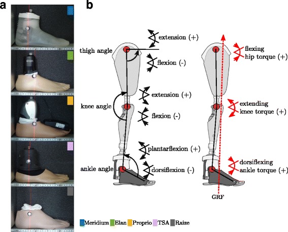
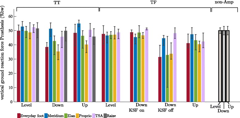
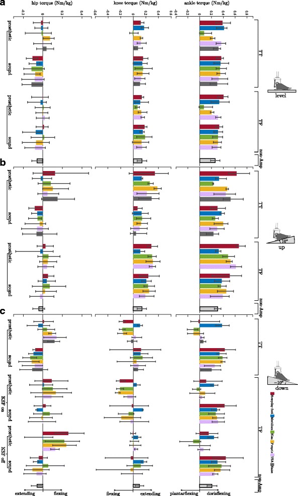
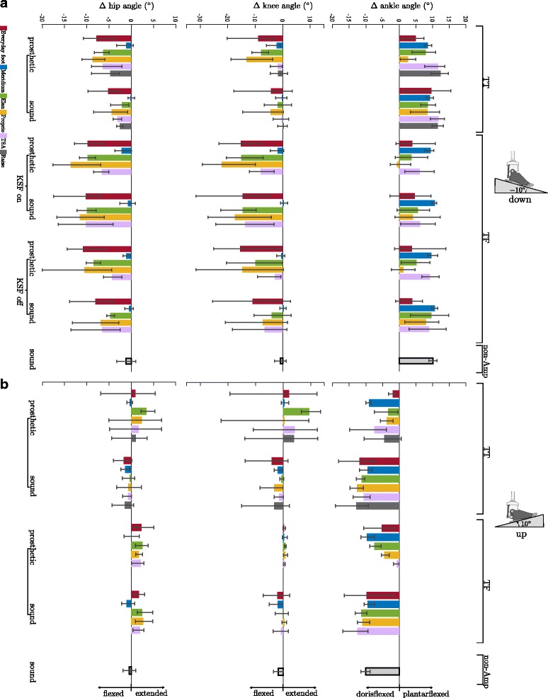
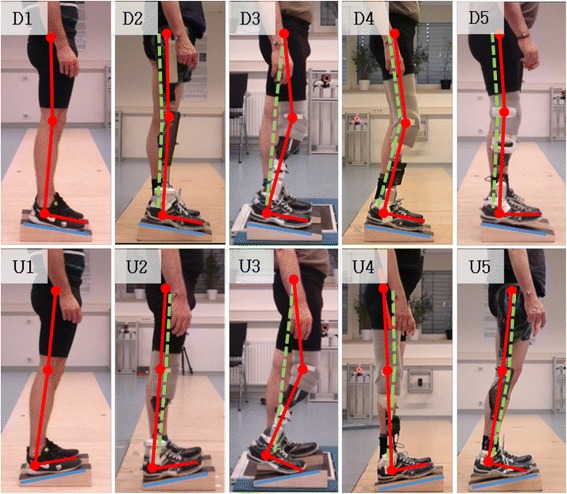
Methods: Four unilateral transtibial and four unilateral transfemoral amputees participated in the study. Each of the subjects wore five different microprocessor-controlled prosthetic feet in addition to their everyday feet. The subjects were asked to stand on slopes of different inclinations (level ground, upward slope of 10°, and downward slope of -10°). Vertical ground reaction forces, joint torques and joint angles in the sagittal plane were measured for both legs separately for the different situations and compared to a non-amputee reference group.

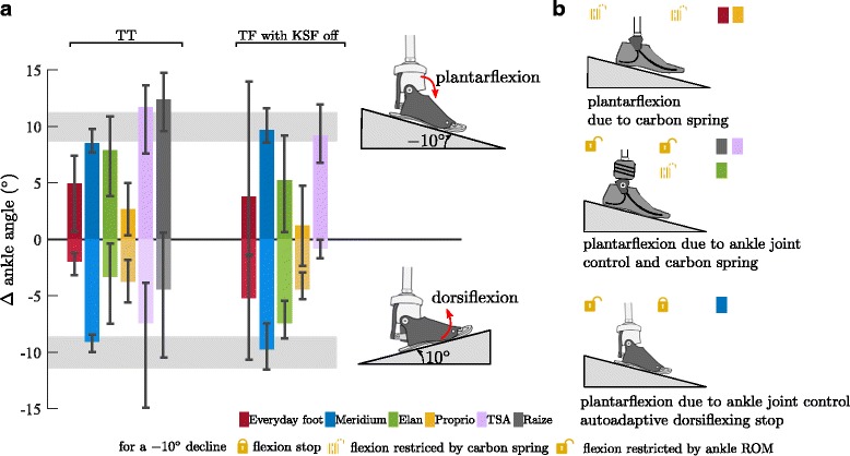
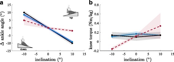
Results: Differences in the biomechanical parameters were observed between the different prosthetic feet and compared to the reference group for the investigated situations. They were most prominent while standing on a downward slope. For example, on the prosthetic side, the vertical ground reaction force is reduced by about 20%, and the torque about the knee acts to flex the joint for feet that are not capable of a full adaptation to the downward slope. In contrast, fully adaptable feet with an auto-adaptive dorsiflexion stop show no changes in vertical ground reaction forces and knee extending torques.

Conclusions: A prosthetic foot that provides both, an auto-adaptive dorsiflexion stop and a sufficient range of motion for fully adapting to inclinations appears to be the key element in the prosthetic fitting for standing on inclinations in lower limb amputees. In such situations, this prosthetic concept appears superior to both, conventional feet with passive structures as well as feet that solely provide a sufficient range of motion. The results also indicate that both, transfemoral and transtibial amputees benefit from such a foot.

Keywords: Amputee; Biomechanics; Microprocessor-controlled prosthetic feet; Prosthetic; Prosthetic knee; Standing; Strategies in standing.


Conflict of interest statement

Ethics approval and consent to participate

The study was conducted in accordance with the Declaration of Helsinki and approved by the ethic committee of the University Medical Center Göttingen (UMG). Prior to the participation each subject got a detailed explanation about the study, and a written informed consent was obtained from all subjects.

Competing interests

All authors are fulltime employees of Otto Bock. The feet investigated in the study are from different prosthetic manufacturers (Otto Bock, Fillauer, Össur, Blachford).

Publisher’s Note

Springer Nature remains neutral with regard to jurisdictional claims in published maps and institutional affiliations.

Figures

Fig. 1
Fig. 1
Definition of leg joint angles. a Modeled ankle joint position for the different MPF. The marker position corresponds to the mechanical joint axis of the foot. b Definition of used leg joint angles and sign convention
Fig. 2
Fig. 2
Vertical ground reaction forces for TT and TF amputees sorted by foot and situation. The investigated feet are (from left to right): Everyday foot (red), Meridium (blue), Elan (green), Proprio (orange), TSA (purple), and Raize (grey only TT). The error bars specify maximum and minimum within the group. For comparison, the mean and SD values of the non-amputee group (black-framed) are given, too. Note, that the colored bars give the vGRF of the prosthetic side (mean values in % body weight) while the vGRF of the sound side is the remaining amount (vGRF(sound) = 100 – vGRF(prosthetic) in %)
Fig. 3
Fig. 3
Leg joint torques for standing on level ground, on an upward slope, and on a downward slope. a level ground, (b) on an upward slope of 10°, and (c) on an downward slope of −10° for TT and TF amputees. Sorted by foot and situation. Feet are (from left to right): Everyday foot (red), Meridium (blue), Elan (green), Proprio (orange), TSA (purple), and Raize (grey only TT). The error bars specify maximum and minimum within the group for the amputees. Mean and SD values of the non-amputee group (black-framed) are given, too. Mean values in Nm/kg. Note, for amputees the knee (TT) and hip (TT & TF) torques on the prosthetic side and all of the sound side are the crucial ones (not the torques acting on the prosthesis). From an engineering point of view the torques acting on the prosthesis are also interesting
Fig. 4
Fig. 4
Ankle angle adaptations in the prosthetic feet to upward and downward slopes. a Ankle angle adaptation in the prosthetic feet compared to level standing for TT and TF (KSF off) subjects for standing on an upward and downward slope of 10°. Feet are (from left to right): Everyday foot (red), Meridium (blue), Elan (green), Proprio (orange), TSA (purple), and Raize (grey only TT). The error bars specify maximum and minimum within the group for the amputees. Range of adaptation (±SD) found in the non-amputee group is shaded in gray. Note that due to compensatory strategies in knee and hip the ROM of the MPF might not be exploited. b Mechanisms causing plantarflexion while standing on a −10° downward slope
Fig. 5
Fig. 5
Leg joint angles for standing on a downward and upward slope. a downward slope of −10° and (b) upward slope of 10° for TT and TF amputees sorted by foot and side. Feet are (from left to right): Everyday foot (red), Meridium (blue), Elan (green), Proprio (orange), TSA (purple), and Raize (grey only TT). Values shown are differences to level standing. The error bars specify maximum and minimum within the group for the amputees. The mean and SD values of the non-amputee group (black-framed) are given, too
Fig. 6
Fig. 6
Individual postural strategies in standing on inclinations. Strategies used while standing on an upward slope of 10° (lower array) and on a downward slope (upper array). The individual posture is highlighted with red (prosthetic side) and dashed-green (sound side) bars for amputees (D2-D5 and U2-U5). The pictures in the first column (D1 and U1) show the posture of a non-amputee. It is almost identical with the posture of amputees equipped with a prosthetic foot that adapt fully to the inclinations and apply a dorisflexing stop (D2 and U2). The amputees use compensational postures if equipped with feet not adapting to the incline (D3-D5 and U3-U5). Note that the different individual compensation strategies shown in D3-D5 are the outcome of the same MPF
Fig. 7
Fig. 7
Interpolation to a range of inclinations. a Ankle angle adaptations in the prosthetic feet compared to level standing and (b) knee torques for TT. Feet are: Everyday foot (red), Meridium (blue), non-Amp (black). The shaded areas are the corresponding SD

References

    1. Segal AD, Orendurff MS, Klute GK, et al. Kinematic and kinetic comparisons of transfemoral amputee gait using C-leg and Mauch SNS prosthetic knees. J Rehabil Res Dev. 2006;43:857–870. doi: 10.1682/JRRD.2005.09.0147. - DOI - PubMed
    1. Kaufman KR, Levine JA, Brey RH, et al. Gait and balance of transfemoral amputees using passive mechanical and microprocessor-controlled prosthetic knees. Gait Posture. 2007;26:489–493. doi: 10.1016/j.gaitpost.2007.07.011. - DOI - PubMed
    1. Schmalz T, Blumentritt S, Marx B. Biomechanical analysis of stair ambulation in lower limb amputees. Gait Posture. 2007;25:267–278. doi: 10.1016/j.gaitpost.2006.04.008. - DOI - PubMed
    1. Bellmann M, Schmalz T, Blumentritt S. Comparative biomechanical analysis of current microprocessor-controlled prosthetic knee joints. Arch Phys Med Rehabil. 2010;91:644–652. doi: 10.1016/j.apmr.2009.12.014. - DOI - PubMed
    1. Bellmann M, Schmalz T, Ludwigs E, Blumentritt S. Immediate effects of a new microprocessor-controlled prosthetic knee joint: a comparative biomechanical evaluation. Arch Phys Med Rehabil. 2012;93:541–549. doi: 10.1016/j.apmr.2011.10.017. - DOI - PubMed