

Adaptive integrated parallel reception, excitation, and shimming (iPRES-A) with microelectromechanical systems switches
- PMID: 29148102
- PMCID: PMC5876104
- DOI: 10.1002/mrm.27007
Adaptive integrated parallel reception, excitation, and shimming (iPRES-A) with microelectromechanical systems switches
Abstract
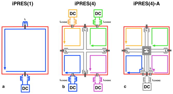
Purpose: Integrated parallel reception, excitation, and shimming coil arrays with N shim loops per radio-frequency (RF) coil element (iPRES(N)) allow an RF current and N direct currents (DC) to flow in each coil element, enabling simultaneous reception/excitation and shimming of highly localized B0 inhomogeneities. The purpose of this work was to reduce the cost and complexity of this design by reducing the number of DC power supplies required by a factor N, while maintaining a high RF and shimming performance.
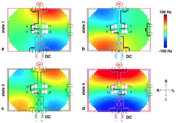
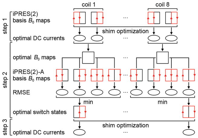
Methods: In the proposed design, termed adaptive iPRES(N) (iPRES(N)-A), each coil element only requires one DC power supply, but uses microelectromechanical systems switches to adaptively distribute the DC current into the appropriate shim loops to generate the desired magnetic field for B0 shimming. Proof-of-concept phantom experiments with an iPRES(2)-A coil and simulations in the human abdomen with an 8-channel iPRES(4)-A body coil array were performed to demonstrate the advantages of this innovative design.
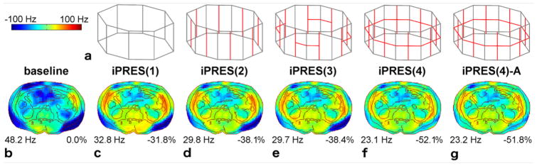
Results: The iPRES(2)-A coil showed no loss in signal-to-noise ratio and provided a much more effective correction of highly localized B0 inhomogeneities and geometric distortions than an equivalent iPRES(1) coil (88.2% vs. 32.2% lower B0 root-mean-square error). The iPRES(4)-A coil array showed a comparable shimming performance as that of an equivalent iPRES(4) coil array (52.6% vs. 54.2% lower B0 root-mean-square error), while only requiring 8 instead of 32 power supplies.
Conclusion: The iPRES(N)-A design retains the ability of the iPRES(N) design to shim highly localized B0 inhomogeneities, while drastically reducing its cost and complexity. Magn Reson Med 80:371-379, 2018. © 2017 International Society for Magnetic Resonance in Medicine.
Keywords: B0 shimming; RF coil; coil array; shim coil; switches.
© 2017 International Society for Magnetic Resonance in Medicine.
Figures


Similar articles
-
Recent Advances in Radio-Frequency Coil Technologies: Flexible, Wireless, and Integrated Coil Arrays.J Magn Reson Imaging. 2022 Apr;55(4):1026-1042. doi: 10.1002/jmri.27865. Epub 2021 Jul 29. J Magn Reson Imaging. 2022. PMID: 34324753 Free PMC article. Review.
-
Integrated parallel reception, excitation, and shimming (iPRES) with multiple shim loops per radio-frequency coil element for improved B0 shimming.Magn Reson Med. 2017 May;77(5):2077-2086. doi: 10.1002/mrm.26267. Epub 2016 May 13. Magn Reson Med. 2017. PMID: 27174387 Free PMC article.
-
Integrated parallel reception, excitation, and shimming (iPRES).Magn Reson Med. 2013 Jul;70(1):241-7. doi: 10.1002/mrm.24766. Epub 2013 Apr 29. Magn Reson Med. 2013. PMID: 23629974 Free PMC article.
-
Integrated radio-frequency/wireless coil design for simultaneous MR image acquisition and wireless communication.Magn Reson Med. 2019 Mar;81(3):2176-2183. doi: 10.1002/mrm.27513. Epub 2018 Sep 14. Magn Reson Med. 2019. PMID: 30277273 Free PMC article.
-
Advancements in MR hardware systems and magnetic field control: B0 shimming, RF coils, and gradient techniques for enhancing magnetic resonance imaging and spectroscopy.Psychoradiology. 2024 Aug 14;4:kkae013. doi: 10.1093/psyrad/kkae013. eCollection 2024. Psychoradiology. 2024. PMID: 39258223 Free PMC article. Review.
Cited by
-
An orthogonal shim coil for 3T brain imaging.Magn Reson Med. 2020 Apr;83(4):1499-1511. doi: 10.1002/mrm.28010. Epub 2019 Oct 21. Magn Reson Med. 2020. PMID: 31631391 Free PMC article.
-
Enhancing Whole-Brain Magnetic Field Homogeneity for 3D-Magnetic Resonance Spectroscopic Imaging with a Novel Unified Coil: A Preliminary Study.Cancers (Basel). 2024 Mar 21;16(6):1233. doi: 10.3390/cancers16061233. Cancers (Basel). 2024. PMID: 38539565 Free PMC article.
-
Recent Advances in Radio-Frequency Coil Technologies: Flexible, Wireless, and Integrated Coil Arrays.J Magn Reson Imaging. 2022 Apr;55(4):1026-1042. doi: 10.1002/jmri.27865. Epub 2021 Jul 29. J Magn Reson Imaging. 2022. PMID: 34324753 Free PMC article. Review.
-
An iPRES-W Coil Array for Simultaneous Imaging and Wireless Localized B0 Shimming of the Cervical Spinal Cord.Magn Reson Med. 2022 Aug;88(2):1002-1014. doi: 10.1002/mrm.29257. Epub 2022 Apr 25. Magn Reson Med. 2022. PMID: 35468243 Free PMC article.
-
Application of an integrated radio-frequency/shim coil technology for signal recovery in fMRI.Magn Reson Med. 2021 Dec;86(6):3067-3081. doi: 10.1002/mrm.28925. Epub 2021 Jul 20. Magn Reson Med. 2021. PMID: 34288086 Free PMC article.
References
-
- Roméo F, Hoult DI. Magnet field profiling: Analysis and correcting coil design. Magn Reson Med. 1984;1(1):44–65. - PubMed
-
- Topfer R, Starewicz P, Lo KM, Metzemaekers K, Jette D, Hetherington H, Stikov N, Cohen-Adad J. A 24-channel shim array for the human spinal cord: Design, evaluation, and application. Magn Reson Med. 2016;76:1604–1611. - PubMed
Publication types
MeSH terms
Grants and funding
LinkOut - more resources
Full Text Sources
Other Literature Sources
Medical
