. 2017 Nov 17;12(11):e0187513.
doi: 10.1371/journal.pone.0187513. eCollection 2017.

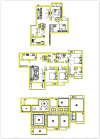
Automatic structural scene digitalization

Affiliations

Automatic structural scene digitalization

Rui Tang et al. PLoS One. .

Retraction in

Abstract

In this paper, we present an automatic system for the analysis and labeling of structural scenes, floor plan drawings in Computer-aided Design (CAD) format. The proposed system applies a fusion strategy to detect and recognize various components of CAD floor plans, such as walls, doors, windows and other ambiguous assets. Technically, a general rule-based filter parsing method is fist adopted to extract effective information from the original floor plan. Then, an image-processing based recovery method is employed to correct information extracted in the first step. Our proposed method is fully automatic and real-time. Such analysis system provides high accuracy and is also evaluated on a public website that, on average, archives more than ten thousands effective uses per day and reaches a relatively high satisfaction rate.


Conflict of interest statement

Competing Interests: Kujiale.com provided support in the form of salary to Rui Tang. This does not alter the authors’ adherence to all the PLoS ONE policies on sharing data and materials.

Figures

Fig 1
Fig 1. Different ways to draw a wall with a window and a door.
The variable graphic symbols pose challenges for automatically recognition of objects in CAD drawings [12].
Fig 2
Fig 2. Work flow of the floor plan analysis system.
Starting with putting in raw data, followed by the process of standardisation, filtering and rasterising correcting. As a result, walls, windows and doors can be detected.
Fig 3
Fig 3. An example of multiple floor plans in a single CAD drawing; systematic clustering is employed to classify lines based on Euler distance.
Fig 4
Fig 4. Raw data as input of a floor plan.
Parallel lines are targeted in the process of filtering, based on the assumption that they represent walls.
Fig 5
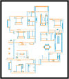
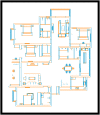
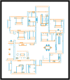
Fig 5. Production of a gradient filter, with the orange and blue lines representing horizontal filtered lines and vertical set, respectively.
(Threshold: pi/12.)
Fig 6
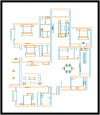
Fig 6. Production of a length filter, with the red and blue lines representing the filtering result after it is applied (Threshold: 2mm).
Fig 7
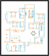
Fig 7. Production of fill gap and merge lines processing.
The gap filling process applies to lines that are within 1mm of each other.
Fig 8
Fig 8. Multi-parallel lines with same gaps to represent windows.
Applying a line split function to split long lines into segmented short lines, because the outer bounds of windows are connected in walls.
Fig 9
Fig 9. The results after removing multiple-parallel lines.
Inner lines in the multiple parallel lines structure are removed after applying a line-splitting filter.
Fig 10
Fig 10. The results after applying the length filter.
It removes pairs of short parallel lines (less than 90mm) that contribute to a short wall.
Fig 11
Fig 11. Production from applying a connectivity filter, which removes irrelevant lines.
Fig 12
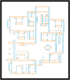
Fig 12. Production of the second fill gap and merge line processing.
This is the process of filling gaps between doors and long lines. The red and blue lines represent Hs7 and Vs7 in Eq 4.9, respectively.
Fig 13
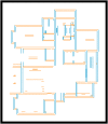
Fig 13. Identify pairs of parallel lines as candidates.
Parallel lines in the vertical and horizontal directions are marked as red and blue, respectively.
Fig 14
Fig 14. Walls are generated from the candidate pairs of parallel lines; the overlapping areas that marked in yellow are walls.
Fig 15
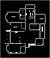
Fig 15. Floor plan must be rasterised before applying the image-parsing method.
This figure shows a rasterised result of raw input data.
Fig 16
Fig 16. Floor plan must be rasterised before applying the image-parsing method.
This figure shows a rasterised result for walls extracted in the filter steps.
Fig 17
Fig 17
Left: An example of connected components in a binary image with three connected components. Right: An example of labelling connected components in a binary image. Connected components in the binary image are identified before being a new unique label.
Fig 18
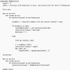
Fig 18. Pseudocode of the connected component labelling algorithm.
Temporary equivalent labels are assigned in the first passes and the smallest label of its equivalent class will replace them in the second pass.
Fig 19
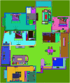
Fig 19. After applying the two-pass algorithm over the image, component labelling result IrawComponent generated.
Fig 20
Fig 20. Wall restoration is the process of tracking each component in the original image and comparing a single one with a wall mask, and this figure shows the final wall extraction result obtained by the proposed system.
Fig 21
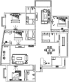
Fig 21. The result of analysing CAD floor plans for three different real-life projects.
The evaluation result proves that the system is able to complete recognition process without user intervention.
Fig 22
Fig 22. Based on the research, we get an average score at 7.71 from 2515 user study samples, which indicates an outstanding performance of the system.
Fig 23
Fig 23. Statistic of our CAD recognition System.
There are over ten thousands request per day.

References

    1. CADFloorPlan. https://en.wikipedia.org/wiki/3Dfloorplan
    1. Dosch P, Masini G. Reconstruction of the 3d structure of a building from the 2d drawings of its floors. In: Document Analysis and Recognition, 1999. ICDAR’99. Proceedings of the Fifth International Conference on. IEEE; 1999. p. 487–490.
    1. Lu T, Yang H, Yang R, Cai S. Automatic analysis and integration of architectural drawings. International Journal of Document Analysis and Recognition (IJDAR). 2007;9(1):31–47. doi: 10.1007/s10032-006-0029-6 - DOI
    1. Or SH, Wong KH, Yu Yk, Chang MM, Kong H. Highly automatic approach to architectural floorplan image understanding & model generation. Pattern Recognition. 2005; p. 25–32.
    1. Macé S, Locteau H, Valveny E, Tabbone S. A system to detect rooms in architectural floor plan images. In: Proceedings of the 9th IAPR International Workshop on Document Analysis Systems. ACM; 2010. p. 167–174.

Publication types

MeSH terms

LinkOut - more resources