

The Perfectly Matched Layer absorbing boundary for fluid-structure interactions using the Immersed Finite Element Method
- PMID: 29151673
- PMCID: PMC5688520
- DOI: 10.1016/j.jfluidstructs.2017.09.002
The Perfectly Matched Layer absorbing boundary for fluid-structure interactions using the Immersed Finite Element Method
Abstract
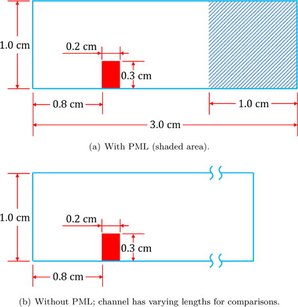
In this work, a non-reflective boundary condition, the Perfectly Matched Layer (PML) technique, is adapted and implemented in a fluid-structure interaction numerical framework to demonstrate that proper boundary conditions are not only necessary to capture correct wave propagations in a flow field, but also its interacted solid behavior and responses. While most research on the topics of the non-reflective boundary conditions are focused on fluids, little effort has been done in a fluid-structure interaction setting. In this study, the effectiveness of the PML is closely examined in both pure fluid and fluid-structure interaction settings upon incorporating the PML algorithm in a fully-coupled fluid-structure interaction framework, the Immersed Finite Element Method. The performance of the PML boundary condition is evaluated and compared to reference solutions with a variety of benchmark test cases including known and expected solutions of aeroacoustic wave propagation as well as vortex shedding and advection. The application of the PML in numerical simulations of fluid-structure interaction is then investigated to demonstrate the efficacy and necessity of such boundary treatment in order to capture the correct solid deformation and flow field without the requirement of a significantly large computational domain.
Figures
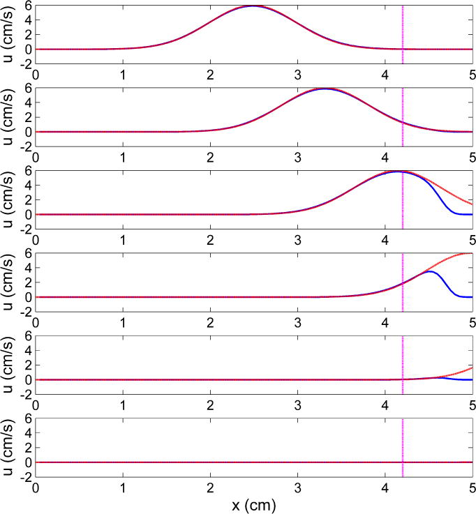
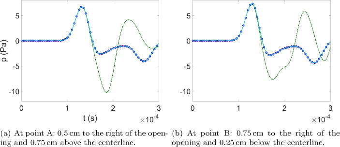
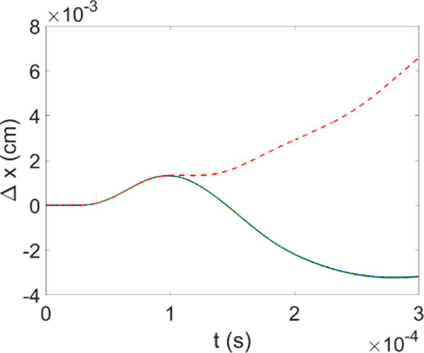
 (blue solid line): numerical solution;
 (red dash line): theoretical
solution in absence of PML; vertical
(red dash line): theoretical
solution in absence of PML; vertical  (magenta dash dot line): interface between the physical domain and PML.
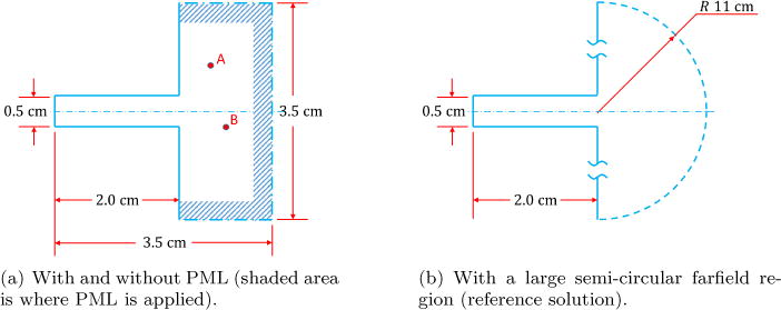
 (cyan solid line): with 0.5 cm-thick PML;
 (red dash line): with 0.25
cm-thick PML;
(red dash line): with 0.25
cm-thick PML;  (green dash dot
line): with no PML;
(green dash dot
line): with no PML;  (blue circle):
with semi-circular farfield region.
(blue circle):
with semi-circular farfield region.
 (blue solid line): with PML;
  (green dash dot line): with large farfield
region;
(green dash dot line): with large farfield
region;  (red dash line): with no
appropriate treatment of outflow boundary.
(red dash line): with no
appropriate treatment of outflow boundary.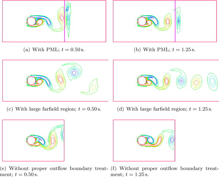
 (blue solid line): fluid
domain with PML;
(blue solid line): fluid
domain with PML;  (green dash dot
line): 8 cm × 1 cm fluid domain;
(green dash dot
line): 8 cm × 1 cm fluid domain;  (red dash line): 2 cm × 1 cm fluid
domain.
(red dash line): 2 cm × 1 cm fluid
domain.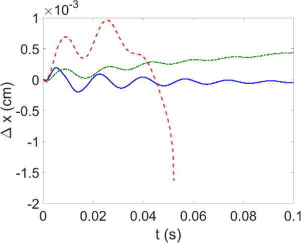
 (blue solid line): fluid
domain with PML;
(blue solid line): fluid
domain with PML;  (green dash dot
line): 8 cm×1 cm fluid domain;
(green dash dot
line): 8 cm×1 cm fluid domain;  (red dash line): 2 cm
× 1 cm fluid domain.
(red dash line): 2 cm
× 1 cm fluid domain.
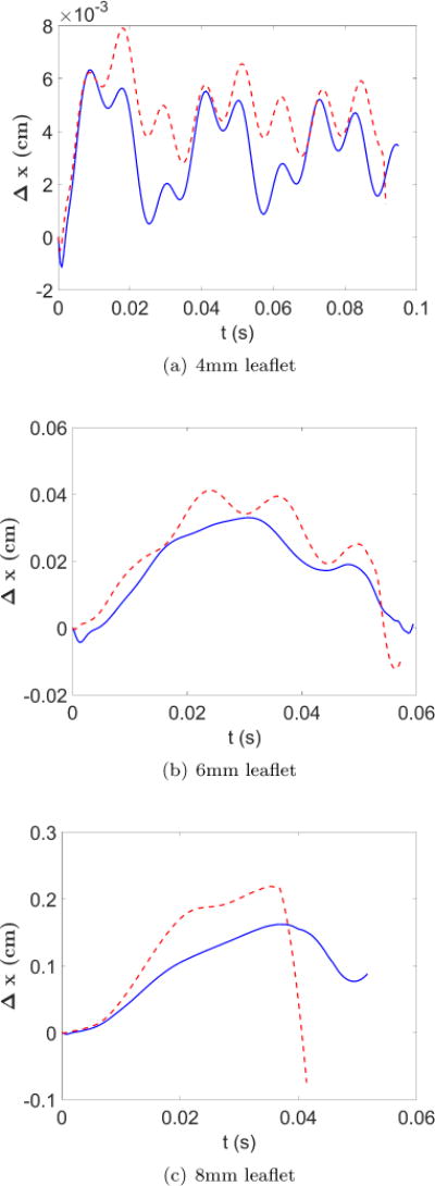
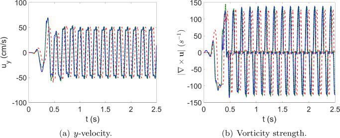
 (red dashed line): Cases
without PML;
(red dashed line): Cases
without PML;  (blue solid line):
Cases with PML.
(blue solid line):
Cases with PML.References
-
- Colonius T. Modeling artificial boundary conditions for compressible flow. Annual Review of Fluid Mechanics. 2004;36:315–345.
-
- Zhou Y, Wang Z. Absorbing boundary conditions for the Euler and Navier–Stokes equations with the spectral difference method. Journal of Computational Physics. 2010;229(23):8733–8749.
-
- Givoli D. Numerical Methods for Problems in Infinite Domains. Elsevier; 2013.
-
- Heywood JG, Rannacher R, Turek S. Artificial Boundaries and Flux and Pressure Conditions for the Incompressible Navier-Stokes Equations. International Journal for Numerical Methods in Fluids. 1996;22:325–352.
-
- Astley J. Infinite elements for wave problems: a review of current formulations and an assessment of accuracy. International Journal for Numerical Methods in Engineering. 2000;49(7):951–976.
Grants and funding
LinkOut - more resources
Full Text Sources
Other Literature Sources