. 2017 Oct 27;18(1):839-856.
doi: 10.1080/14686996.2017.1388135. eCollection 2017.

Manipulating mammalian cell morphologies using chemical-mechanical polished integrated circuit chips

Affiliations

Manipulating mammalian cell morphologies using chemical-mechanical polished integrated circuit chips

Hassan I Moussa et al. Sci Technol Adv Mater. .

Abstract

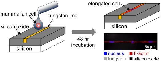
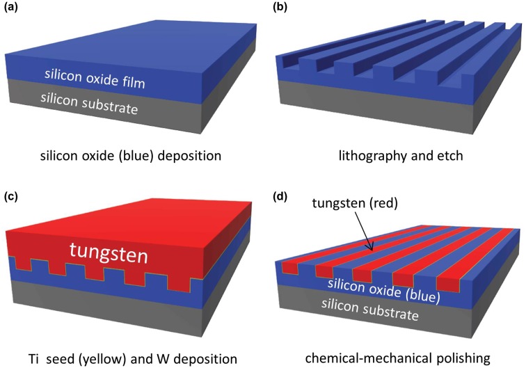
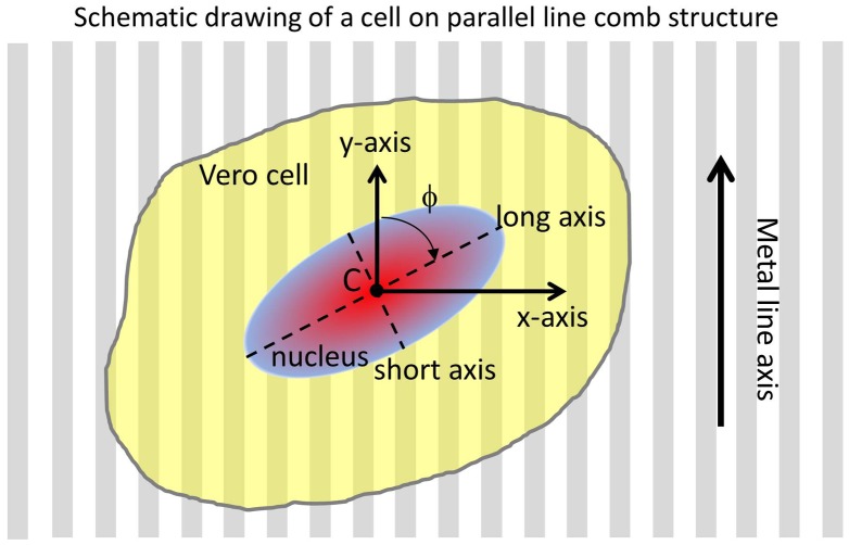
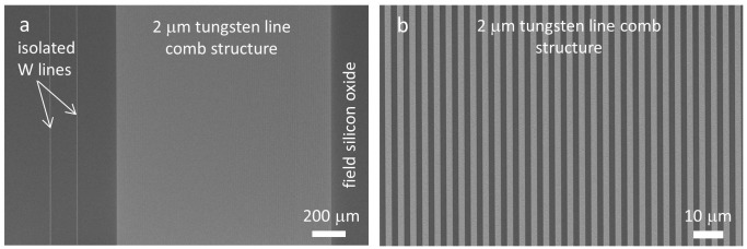
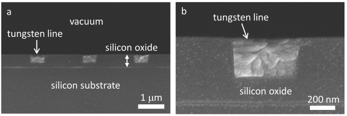
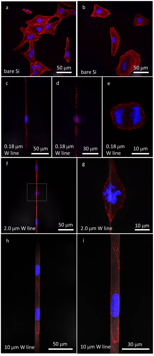
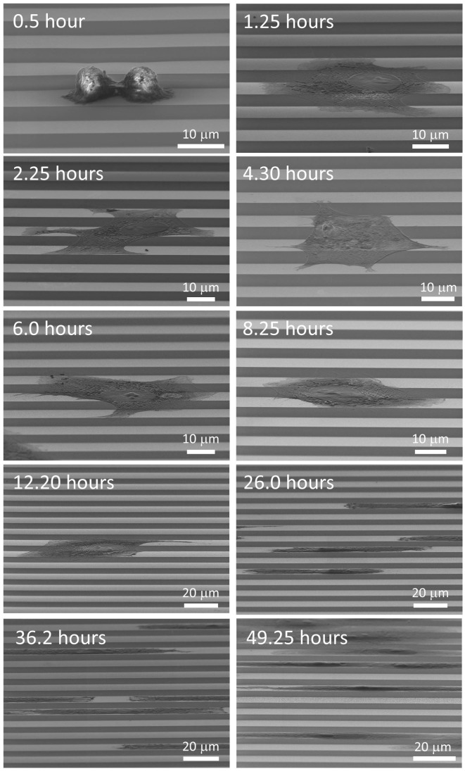
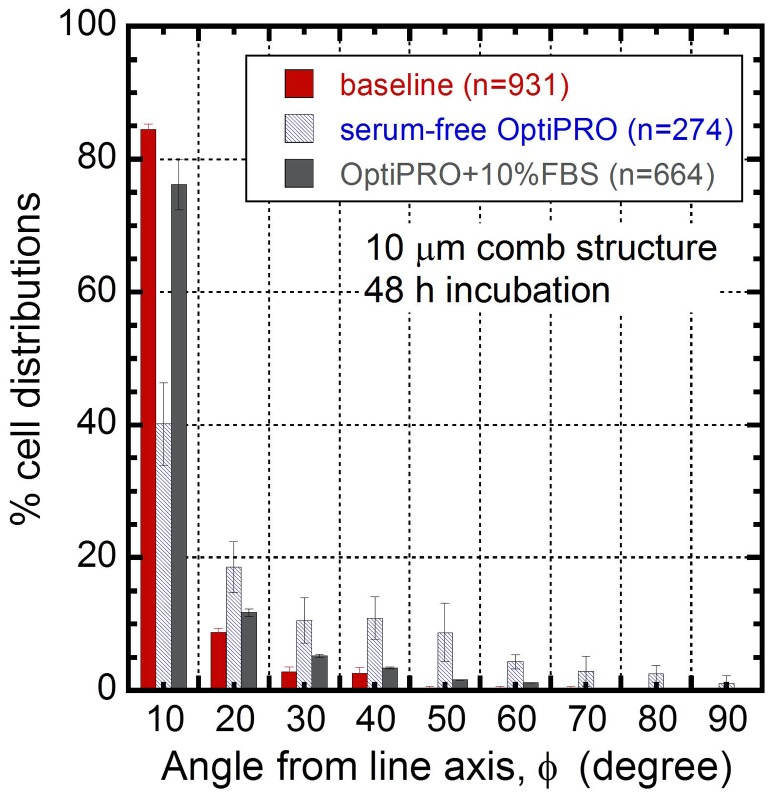
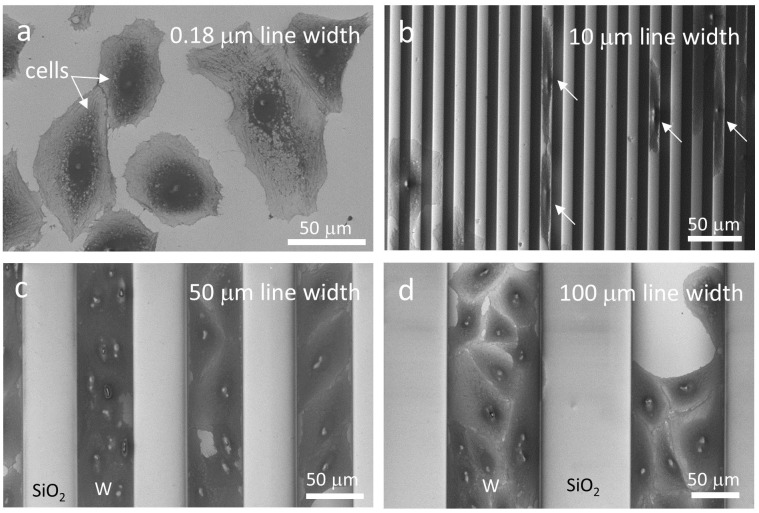
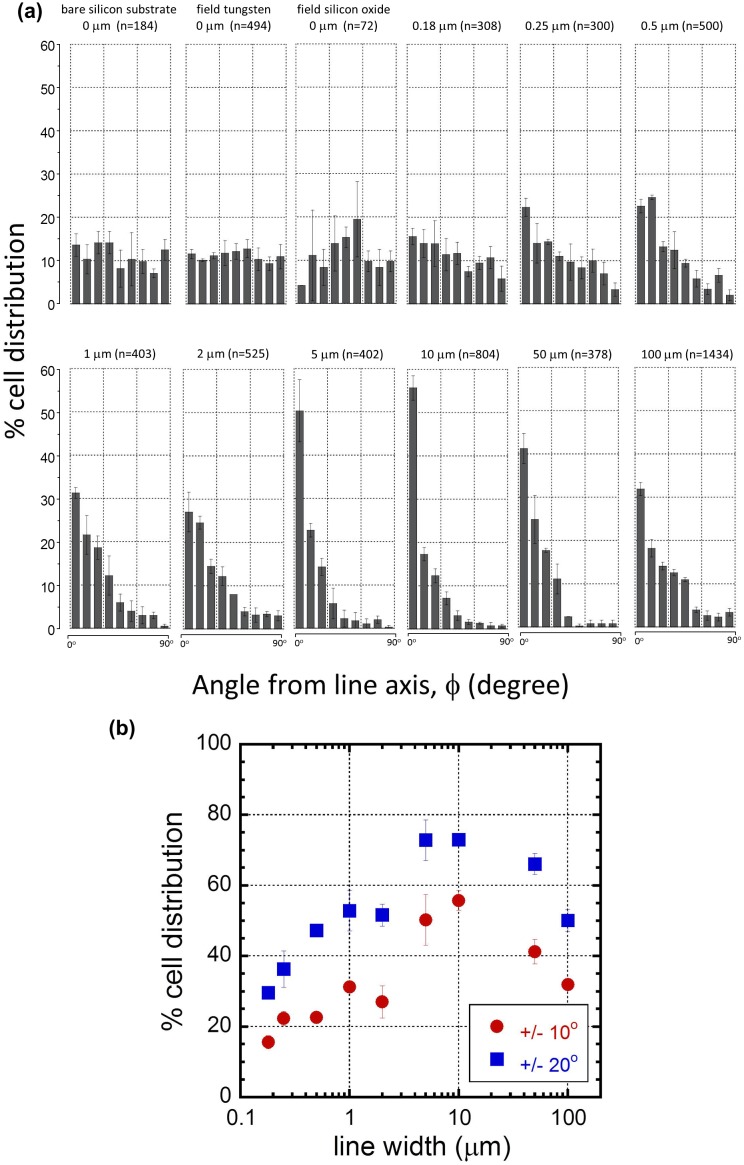
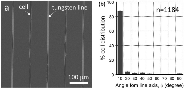
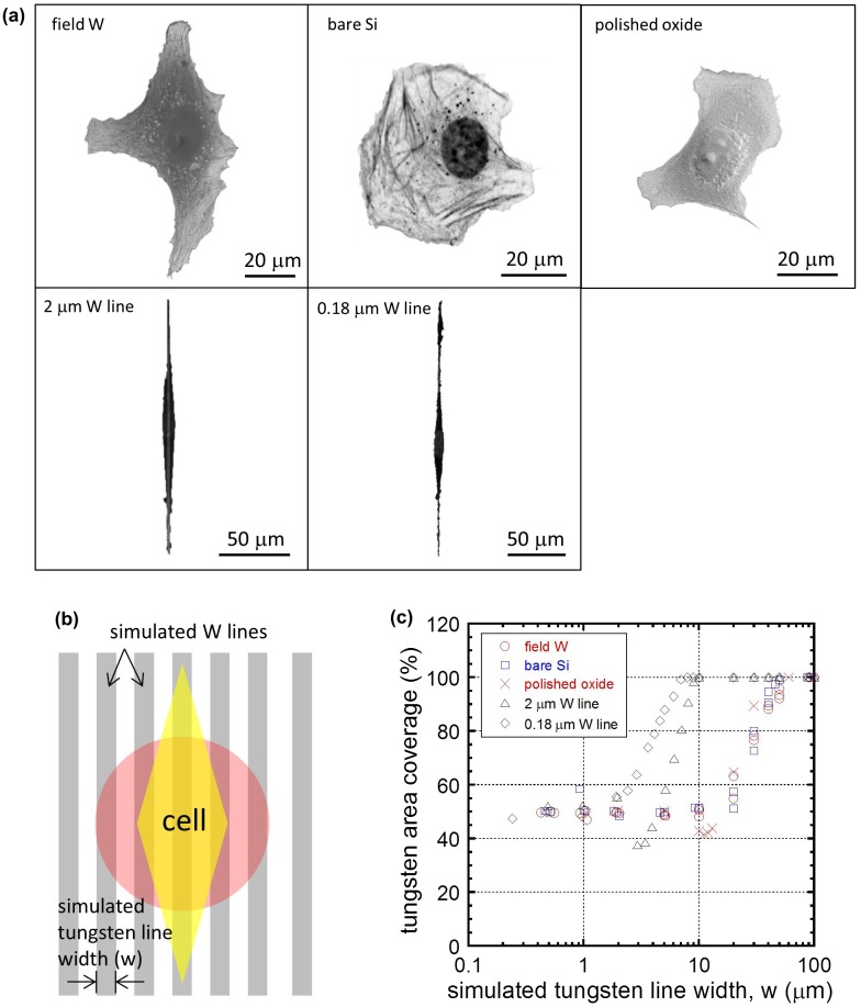
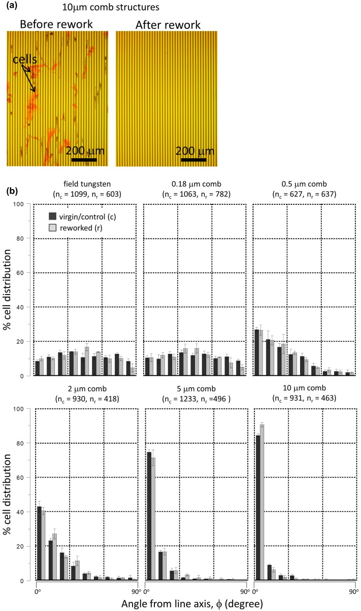
Tungsten chemical-mechanical polished integrated circuits were used to study the alignment and immobilization of mammalian (Vero) cells. These devices consist of blanket silicon oxide thin films embedded with micro- and nano-meter scale tungsten metal line structures on the surface. The final surfaces are extremely flat and smooth across the entire substrate, with a roughness in the order of nanometers. Vero cells were deposited on the surface and allowed to adhere. Microscopy examinations revealed that cells have a strong preference to adhere to tungsten over silicon oxide surfaces with up to 99% of cells adhering to the tungsten portion of the surface. Cells self-aligned and elongated into long threads to maximize contact with isolated tungsten lines as thin as 180 nm. The orientation of the Vero cells showed sensitivity to the tungsten line geometric parameters, such as line width and spacing. Up to 93% of cells on 10 μm wide comb structures were aligned within ± 20° of the metal line axis. In contrast, only ~22% of cells incubated on 0.18 μm comb patterned tungsten lines were oriented within the same angular interval. This phenomenon is explained using a simple model describing cellular geometry as a function of pattern width and spacing, which showed that cells will rearrange their morphology to maximize their contact to the embedded tungsten. Finally, it was discovered that the materials could be reused after cleaning the surfaces, while maintaining cell alignment capability.

Keywords: 102 Porous / Nanoporous / Nanostructured materials; 212 Surface and interfaces; 30 Bio-inspired and biomedical materials; Tungsten; Vero cells; cellular response; chemical-mechanical polish; integrated circuit.


Figures

None
Graphical abstract
Figure 1.
Figure 1.
Schematic drawings depict the specimen fabrication process. The thin titanium (Ti) seed layer is shown in yellow, silicon oxide in blue, and the tungsten (W) layer in red. Note the final specimen surfaces are smooth and flat without protrusions.
Figure 2.
Figure 2.
Schematic drawing of a cell on tungsten/silicon oxide patterned comb structure and their orientation parameters.
Figure 3.
Figure 3.
(a) SEM micrograph of a 2 μm tungsten line comb structures and two isolated tungsten lines with same width. (b) Micrograph shows a close-up image of parallel tungsten/silicon oxide line structures with line widths of 2 μm.
Figure 4.
Figure 4.
(a) Cross-sectional SEM images of dense metal patterns with 0.5 μm wide tungsten lines with 1.5 μm spacing. (b) A high magnification cross-sectional SEM image of a 0.5 μm wide tungsten line.
Figure 5.
Figure 5.
(a) and (b) Confocal fluorescence micrographs of Vero cells on the bare silicon substrate. (c) A non-dividing cell elongated on a 0.18 μm wide isolated tungsten line. (d) and (e) Micrographs of a dividing cell at low and high magnification, respectively. (f) Two non-dividing cells and one dividing cell attached to a 2 μm wide isolated tungsten line. (g) High-magnification image of a dividing nucleus. (h) and (i) Micrographs of cells attached to a 10 μm wide isolated tungsten line at low and high magnifications, respectively. Cell nuclei were labeled with DAPI and appear blue. F-actin microfilaments were stained with red fluorescent phalloidin conjugate and appear red. All cells were incubated for 24 hours.
Figure 6.
Figure 6.
SEM micrographs (70o tilted) of Vero cells on 10 μm comb structures with incubation time between 0.5 and 49.25 hours.
Figure 7.
Figure 7.
Cell orientation distributions on 10 μm comb structures when cultured in baseline (containing 10% FBS), OptiPRO (serum free), and OptiPRO + 10% FBS media. The number of cells inspected (n) on the specimens are displayed in the legend.
Figure 8.
Figure 8.
SEM micrographs revealing changes in cell adhesion characteristics with tungsten line widths of (a) 0.18 μm, (b) 10 μm, (c) 50 μm, and (d) 100 μm. Tungsten line width and silicon oxide spacing in the comb structure are identical in each image.
Figure 9.
Figure 9.
(a) Plots of percent cell distribution as a function of the angle between the nuclei long axis and the metal line axis. They include results from bare silicon substrate, polished field tungsten, polished field silicon oxide, and comb structures with line widths in the range of 0.18 μm to 100 μm. The number of cells inspected in each comb structures (n) is included in each chart. Each bar represents a 10° bin of deviations from the line axis (either +/−), i.e. a cell with a nucleus major axis of −24o would be counted in the second bin from the left in each plot. Error bars correspond to one standard deviation of three independent cell populations. The initial cell concentration of the culture media was 2 ×10⁵ cells/mL. (b) Plot of cell orientation distributions as a function line width.
Figure 10.
Figure 10.
(a) Representative SEM micrographs of a comb structure with 10 μm wide tungsten lines and 90 μm spacing. (b) Plot of percentage cell distribution as a function of angles between the major axis of the nuclei and the metal axis. Parameter n is the total number of cells sampled.
Figure 11.
Figure 11.
(a) Observed cell morphologies on different surfaces (polished field tungsten area – field W; bare silicon – bare Si; polished silicon oxide – polish oxide; surface with isolated 2 μm line – 2 μm W line; surface with 0.18 μm tungsten isolated line – 0.18 μm W line) with a superimposed simulated comb pattern used in the calculation of coverage in (c). (b) Schematic drawing indicating cell orientation relative to the simulated comb structure; the pink circle and yellow diamond represent cells with random and elongated shapes, respectively. (c) Cell-tungsten coverage of cells plotted as a function of simulated tungsten line widths (w).
Figure 12.
Figure 12.
(a) Typical optical micrographs of the same 10 μm comb structures before and after the rework process to remove QT-35 cells. (b) Adherent cell orientations on virgin/control (c) and reworked (r) specimens. nc and nr represent the numbers of cells characterized within each comb structure on virgin and reworked specimens. Error bars correspond to one standard deviation. Initial cell concentration of the culture media is 0.5 × 10⁵ cells/mL.

References

    1. Bourget J, Guillemette M, Veres T, et al. Alignment of cells and extracellular matrix within tissue- engineered substitutes In: Pignatello R, editor. Advances in biomaterials science and biomedical applications. 2013. p. 365–390.
    1. Koubassova NA, Tsaturyan AK. Molecular mechanism of actin – myosin motor in muscle. Biochem. 2011;76(13):1484–1506. - PubMed
    1. Jester JV, Petroll WM, Cavanagh HD. Corneal stromal wound healing in refractive surgery: the role of myofibroblasts. Prog Retin Eye Res. 1999;18(3):311–356. 10.1016/S1350-9462(98)00021-4 - DOI - PubMed
    1. Holzapfel GA, Sommer G, Gasser CT, et al. Determination of layer-specific mechanical properties of human coronary arteries with nonatherosclerotic intimal thickening and related constitutive modeling. Am J Physiol Hear Circ Physiol. 2005;289:H2048–H2058. 10.1152/ajpheart.00934.2004 - DOI - PubMed
    1. Robert L, Legeais JM, Robert AM, et al. Corneal collagens. Pathol Biol (Paris). 2001;49:353–363. 10.1016/S0369-8114(01)00144-4 - DOI - PubMed