. 2018 Feb;31(1):7-18.
doi: 10.1007/s10334-017-0665-5. Epub 2017 Nov 24.

An 8-channel Tx/Rx dipole array combined with 16 Rx loops for high-resolution functional cardiac imaging at 7 T

Affiliations

An 8-channel Tx/Rx dipole array combined with 16 Rx loops for high-resolution functional cardiac imaging at 7 T

Bart R Steensma et al. MAGMA. 2018 Feb.

Abstract

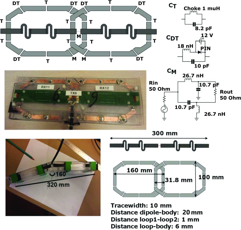
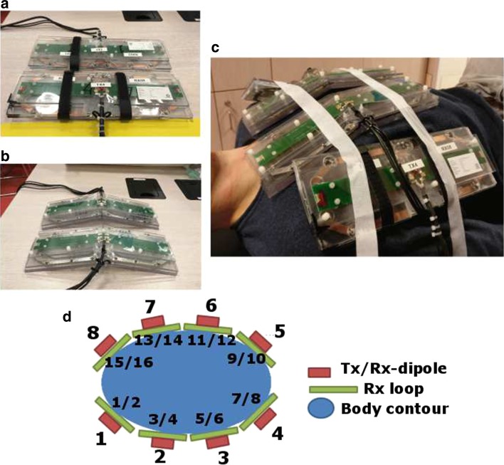
Objective: To demonstrate imaging performance for cardiac MR imaging at 7 T using a coil array of 8 transmit/receive dipole antennas and 16 receive loops.

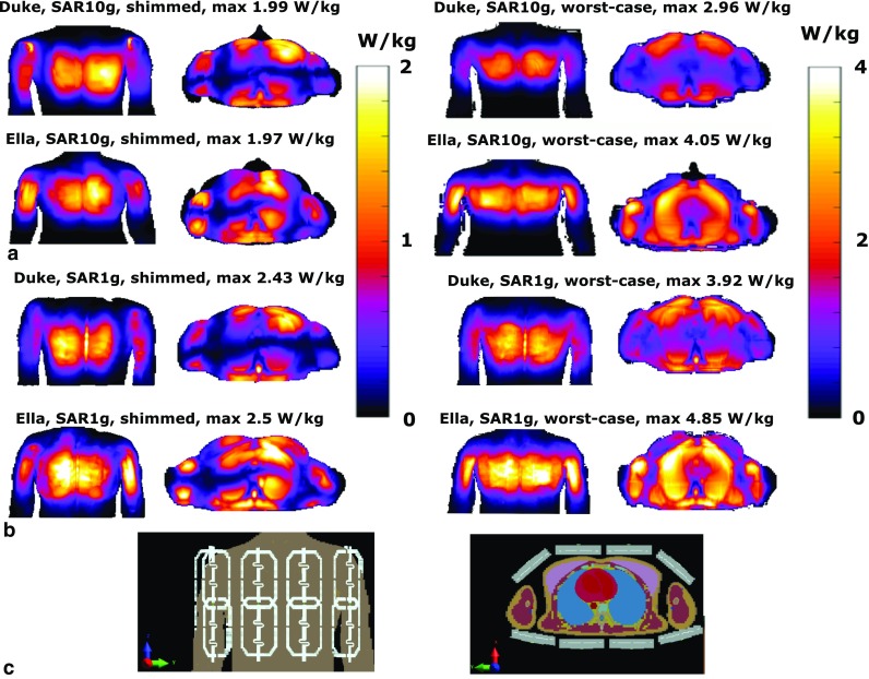
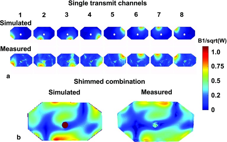
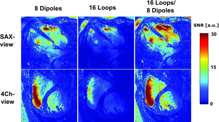
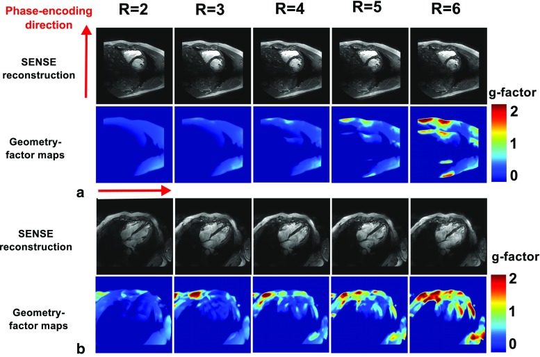
Materials and methods: An 8-channel dipole array was extended by adding 16 receive-only loops. Average power constraints were determined by electromagnetic simulations. Cine imaging was performed on eight healthy subjects. Geometrical factor (g-factor) maps were calculated to assess acceleration performance. Signal-to-noise ratio (SNR)-scaled images were reconstructed for different combinations of receive channels, to demonstrate the SNR benefits of combining loops and dipoles.

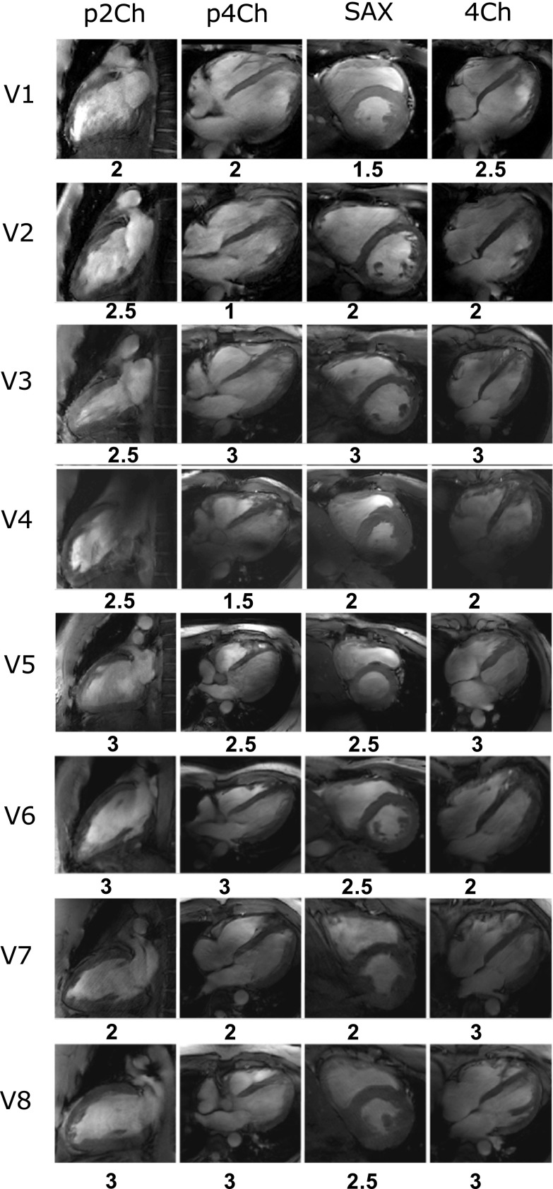
Results: The overall image quality of the cardiac functional images was rated a 2.6 on a 4-point scale by two experienced radiologists. Imaging results at different acceleration factors demonstrate that acceleration factors up to 6 could be obtained while keeping the average g-factor below 1.27. SNR maps demonstrate that combining loops and dipoles provides a more than 50% enhancement of the SNR in the heart, compared to a situation where only loops or dipoles are used.

Conclusion: This work demonstrates the performance of a combined loop/dipole array for cardiac imaging at 7 T. With this array, acceleration factors of 6 are possible without increasing the average g-factor in the heart beyond 1.27. Combining loops and dipoles in receive mode enhances the SNR compared to receiving with loops or dipoles only.

Keywords: Cardiac imaging; Dipole antennas; RF coil arrays; Ultrahigh field.


Conflict of interest statement

Conflict of interest

The authors declare they have no conflict of interest.

Ethical approval

All procedures performed in studies involving human participants were in accordance with the ethical standards of the institutional and/or national research committee and with the 1964 Helsinki Declaration and its later amendments or comparable ethical standards.

Informed consent

Informed consent was obtained from all individual participants included in the study.

Figures

Fig. 1
Fig. 1
Schematic overview of a single-loop dipole element. a Shows a model of the loops and the dipoles and indicates the position of the tuning, detuning and matching circuitry. A lattice balun was used for matching both the loops and the dipoles. b Shows a photograph of a single-loop dipole element. c Shows the detuning and matching circuitry. d Shows one of the two elements that is adapted to the curvature of the chest, by bending both ends of a single element. e Shows the sizes of the loop and dipole elements
Fig. 2
Fig. 2
Schematic overview of the imaging setup. a Shows two elements consisting of a Tx/Rx antenna and two Rx loops. b Shows the two elements that are adapted to fit on the chest. c Shows a schematic drawing of the setup on a torso model. d Shows the transmit setup on a male volunteer. e Shows a noise covariance matrix on an exemplary volunteer
Fig. 3
Fig. 3
a Coronal and transverse maximum intensity projections of SAR10g for the Duke and Ella model. Results are normalized to 1 W of input power for every input channel, using a total input power of 8 W. Input transmit phases are used to maximize average B 1+ in the heart for the image on the left. The image on the right displays the worst-case SAR. b Shows a voxelized model of Duke from a frontal and transverse point of view
Fig. 4
Fig. 4
Phantom simulation setup. a Shows simulated (top) and measured (bottom) B1 + maps on the ethylene–glycol phantom. b Shows the same B1 + maps, now both combined using the same transmit phases
Fig. 5
Fig. 5
Pseudo two-chamber views (p2Ch), pseudo four-chamber views (p4Ch), short-axis views (SAX) and four-chamber views (4Ch) for eight volunteers. Phase-only shimming was applied to maximize the signal in three transverse slices for each individual volunteer. The same transmit phases were used for all acquisitions. All images were acquired with a resolution of 1.3 × 1.3 × 8 mm3, and an average scan time of 10 s. The overall image quality rating is displayed underneath each separate image
Fig. 6
Fig. 6
Four-chamber views using 2D cine acquisitions, at different spatial resolutions. All images were acquired with the same imaging parameters as the cine acquisition shown in Fig. 4, with an AP acceleration factor R2 and at different spatial resolutions. Acquisition time increased from 10 to 12 and 17 s. The bottom row shows the same images but zoomed in on the right cardiac chamber. At high resolution, improved depiction of the myocardial trabeculae in the right ventricular wall can be seen
Fig. 7
Fig. 7
SNR-scaled images for a single volunteer in the SAX view and the 4Ch view. The separate contributions of the loop and dipole elements are displayed here. Phase shimming was applied on three transverse slices through the heart for all volunteers, and the same shim settings were used for all acquisitions. Images were acquired at a resolution of 1.1 × 1.1 × 2.5 mm3, at an average scan time of 20 s
Fig. 8
Fig. 8
g-factor maps for different SENSE acceleration factors (R = 2 to R = 6) on a single volunteer in the SAX view and the 4Ch view. Increasing the acceleration factors increases the g-factor in the heart. Phase shimming was applied on three transverse slices through the heart for all volunteers; the same shim settings were used for all acquisitions. Images were acquired at a resolution of 1.1 × 1.1 × 2.5 mm3, with scantimes ranging from 20 to 7 s

References

    1. van Elderen SGC, Versluis MJ, Westenberg JJM, Agarwal H, Smith NB, Stuber M, de Roos A, Webb AG. Right coronary MR angiography at 7 T: a direct quantitative and qualitative comparison with 3 T in young healthy volunteers. Radiology. 2010;257:1527–1315. doi: 10.1148/radiol.100615. - DOI - PMC - PubMed
    1. Raaijmakers AJE, Aidi HE, Versluis M, Webb A, Lamb HJ, Luijten PR, Berg CAT Van Den, Leiner T (2014) Comprehensive coronary artery imaging at 7.0 T: Proof of feasibility. In: Proceedings of the 22th scientific meeting, International Society Magnetic Resonance in Medicine, Milan, p 3660
    1. Niendorf T, Paul K, Oezerdem C, Graessl A, Klix S, Huelnhagen T, Hezel F, Rieger J, Waiczies H, Frahm J, Nagel AM, Oberacker E. W(h)ither human cardiac and body magnetic resonance at ultrahigh fields? technical advances, practical considerations, applications, and clinical opportunities. NMR Biomed. 2015;29:1173–1197. doi: 10.1002/nbm.3268. - DOI - PubMed
    1. Niendorf T, Graessl A, Dieringer MA, Kraus O, Santoro D, Fuchs K, Hezel F, Waiczies S, Itterman B, Winter L. Progress and promises of human cardiac magnetic resonance at ultrahigh fields: a physics perspective. J Magn Reson Imaging. 2013;229:208–222. doi: 10.1016/j.jmr.2012.11.015. - DOI - PubMed
    1. Von Knobelsdorff-Brenkenhoff F, Frauenrath T, Prothmann M, Dieringer MA, Hezel F, Renz W, Kretschel K, Niendorf T, Schulz-Menger J. Cardiac chamber quantification using magnetic resonance imaging at 7 Tesla-a pilot study. Eur Radiol. 2010;20:2844–2852. doi: 10.1007/s00330-010-1888-2. - DOI - PubMed

MeSH terms