. 2017;2(3):1488-1494.
doi: 10.1109/LRA.2017.2668468. Epub 2017 Feb 14.

Through the Eustachian Tube and Beyond: A New Miniature Robotic Endoscope to See Into The Middle Ear

Affiliations

Through the Eustachian Tube and Beyond: A New Miniature Robotic Endoscope to See Into The Middle Ear

Loris Fichera et al. IEEE Robot Autom Lett. 2017.

Abstract

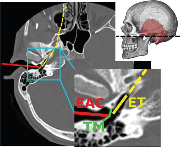
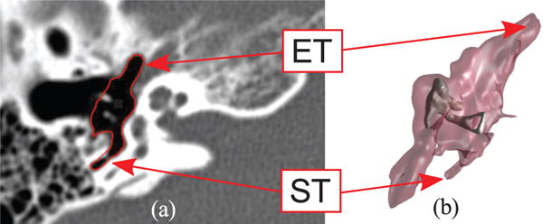
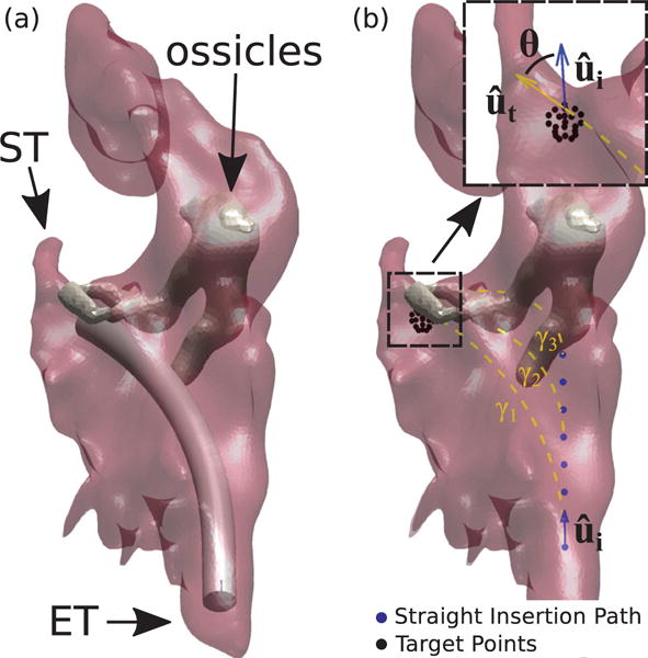
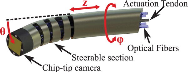
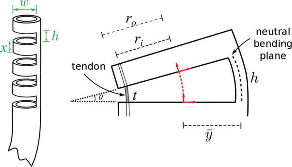
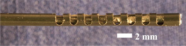
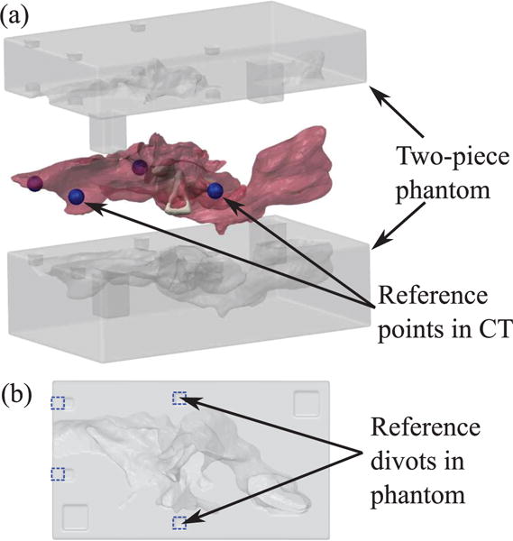
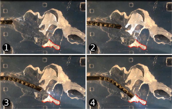
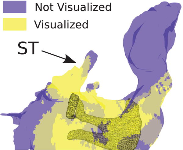
This paper presents a novel miniature robotic endoscope that is small enough to pass through the Eustachian tube and provide visualization of the middle ear (ME). The device features a miniature bending tip previously conceived of as a small-scale robotic wrist that has been adapted to carry and aim a small chip-tip camera and fiber optic light sources. The motivation for trans-Eustachian tube ME inspection is to provide a natural-orifice-based route to the ME that does not require cutting or lifting the eardrum, as is currently required. In this paper, we first perform an analysis of the ME anatomy and use a computational design optimization platform to derive the kinematic requirements for endoscopic inspection of the ME through the Eustachian tube. Based on these requirements, we fabricate the proposed device and use it to demonstrate the feasibility of ME inspection in an anthropomorphic model, i.e. a 3D-printed ME phantom generated from patient image data. We show that our prototype provides > 74% visibility coverage of the sinus tympani, a region of the ME crucial for diagnosis, compared to an average of only 6.9% using a straight, non-articulated endoscope through the Eustachian Tube.

Keywords: Medical Robots and Systems; Steerable Catheters/Needles; Surgical Robotics.


Figures

Fig. 1
Fig. 1
An axial Computed Tomography (CT) scan illustrating the traditional surgical approach to the middle ear through the External Auditory Canal (EAC), in which the eardrum (commonly referred to as Tympanic Membrane or TM in the medical literature) must be surgically incised. Also illustrated is the Eustachian Tube (ET) approach. Adapted from [2]. The dashed line through the skull indicates the position of the axial CT slice.
Fig. 2
Fig. 2
Anatomy of the middle ear: (a) Computed Tomography scan (axial view) where the ME volume has been segmented (red line) through the algorithm described in [23]; (b) 3D geometric model of the same ME generated with the marching cubes algorithm [24]. The external surface of the volume is semi-transparent to show the location of the ossicles, i.e. the chain of bony structures responsible for the transmission of sound to the internal hearing organs. The eustachian tube (ET) and sinus tympani (ST) are visible in the CT scan and the 3D model.
Fig. 3
Fig. 3
Simulated endoscopy of the Middle Ear. Figure (a) shows an example of endoscope insertion: the device shown here has a diameter of 1.40 mm and has been bent in such a way to point towards the sinus tympani (ST). Figure (b) illustrates how insertion paths γi are generated. The endoscope enters the ME following a straight path u^i which coincides with the orientation of the Eustachian Tube (measured in the CT scan). After an initial straight motion of arbitrary length, the endoscope is bent along a constant curvature arc towards a target point. Target points are generated using a spherical grid in the proximity of the target anatomy. Insertion paths found to collide with the ossicles (like γ2 and γ3 in this example) are automatically detected and discarded. The endoscope final orientation u^t defines the overall bending θ.
Fig. 4
Fig. 4
CAD rendering of the proposed miniature robotic endoscope concept. A chip-tip camera is placed on the distal tip of the steerable section. The robotic endoscope has three DoFs. The steerable section is a Nitinol tube containing cut-outs that cause it to bend (θ) as a single tendon attached to the tip is pulled. It can also translate (z) and rotate (ϕ) along its axis. The actuation tendon and camera wiring pass through the interior of the tube.
Fig. 5
Fig. 5
Flexure wrist concept: a number of cutouts are made in the body of a Nitinol tube, creating a compliant region that can be bent using a single tendon. Parameters w and h represent the cutout width and height, while x is the distance between two consecutive cutouts. These parameters plus the total number of cutouts n, determine the maximum bending angle of the wrist. The right figure illustrates the deflection of a single cutout element when the tendon is pulled. The variables ro and ri are the outer and inner diameter of the Nitinol tube, respectively. The angular deflection of a single section, θ, is determined by the height, h, the tendon length within the cutout, t, and the distance between the center of the tube and the neutral bending plane, y^.
Fig. 6
Fig. 6
Endoscope Prototype. There are eight cutouts in a segment of Nitinol Tube having inner diameter (ID) of 1.60 mm and outer diameter (OD) of 1.80 mm. The cutouts have a height of 1 mm and a width of 1.60 mm. In this picture, the chip-tip camera is located at the leftmost end of the tube. A Nitinol wire (diameter = 0.22 mm) is looped around the most distal cutout to provide actuation.
Fig. 7
Fig. 7
Experimental calibration of the prototype.
Fig. 8
Fig. 8
3D printed phantom used in the experiment. (a) Exploded view of two-piece phantom and mesh of ME used to generate the phantom geometry. Reference points (shown as blue spheres) were selected around ME in the CT scan to be used for registration with the phantom. (b) Planar view of bottom side of phantom. Divots corresponding to the reference points in the CT scan are outlined in blue dashed lines. These divots can be localized in the video of the experimental insertion to align the video with the CT scan.
Fig. 9
Fig. 9
Testing of the endoscope tip. The device was inserted into the ME phantom and pointed towards the sinus tympani (ST), which is outlined on the images. Images (1) through (4) show the endoscope position over time.
Fig. 10
Fig. 10
Estimation of ME areas which were visible (yellow) and not visible (blue) during the phantom experiment. We estimated an 74.1% visual coverage of the ST during the experiment.

Similar articles

Cited by

References

    1. Burgner-Kahrs J, Rucker DC, Choset H. Continuum robots for medical applications: A survey. IEEE Transactions on Robotics. 2015;31(6):1261–1280.
    1. Zhang D, Bennett ML, Labadie RF, Noble JH. Simulation of trans-nasal endoscopy of the middle ear for visualization of cholesteatoma. 2015 IEEE 12th International Symposium on Biomedical Imaging (ISBI) 2015 Apr;:1415–1418.
    1. Wallis S, Atkinson H, Coatesworth AP. Chronic otitis media. Postgraduate Medicine. 2015;127(4):391–395. - PubMed
    1. Browning GG, Gatehouse S. The prevalence of middle ear disease in the adult british population. Clinical Otolaryngology & Allied Sciences. 1992;17(4):317–321. - PubMed
    1. Hannula S, Bloigu R, Majamaa K, Sorri M, Mki-Torkko E. Ear diseases and other risk factors for hearing impairment among adults: an epidemiological study. International Journal of Audiology. 2012;51(11):833–840. - PubMed

LinkOut - more resources