. 2017 Dec 5;113(11):2508-2518.
doi: 10.1016/j.bpj.2017.09.032.

Investigating Focal Adhesion Substructures by Localization Microscopy

Affiliations

Investigating Focal Adhesion Substructures by Localization Microscopy

Hendrik Deschout et al. Biophys J. .

Abstract

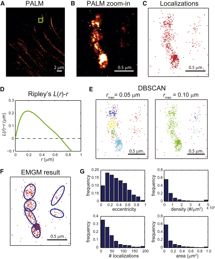
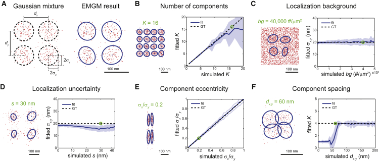
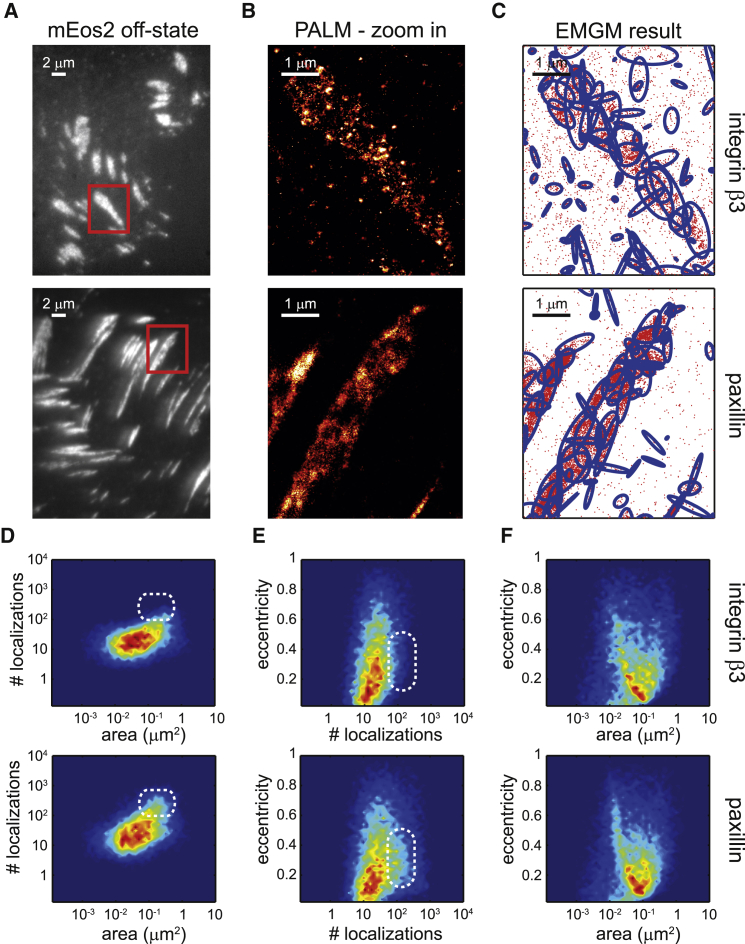
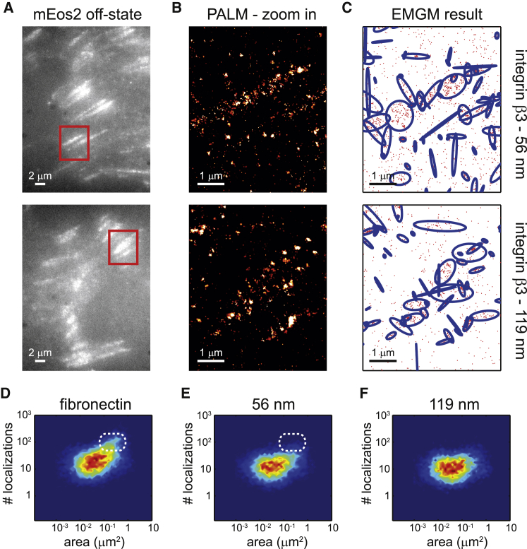
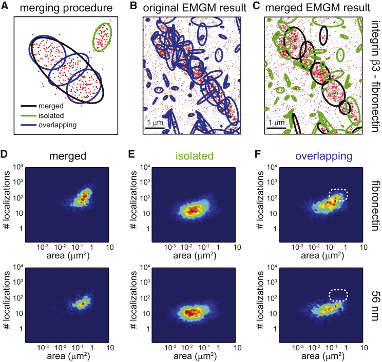
Cells rely on focal adhesions (FAs) to carry out a variety of important tasks, including motion, environmental sensing, and adhesion to the extracellular matrix. Although attaining a fundamental characterization of FAs is a compelling goal, their extensive complexity and small size, which can be below the diffraction limit, have hindered a full understanding. In this study we have used single-molecule localization microscopy (SMLM) to investigate integrin β3 and paxillin in rat embryonic fibroblasts growing on two different extracellular matrix-representing substrates (i.e., fibronectin-coated substrates and specifically biofunctionalized nanopatterned substrates). To quantify the substructure of FAs, we developed a clustering method based on expectation maximization of a Gaussian mixture that accounts for localization uncertainty and background. Analysis of our SMLM data indicates that the structures within FAs, characterized as a Gaussian mixture, typically have areas between 0.01 and 1 μm2, contain 10-100 localizations, and can exhibit substantial eccentricity. Our approach based on SMLM opens new avenues for studying structural and functional biology of molecular assemblies that display substantial varieties in size, shape, and density.


Figures

Figure 1
Figure 1
Application of SMLM clustering algorithms to PALM data of FAs. (A) Given here is a PALM image of a fixed REF cell expressing integrin β3 labeled with mEos2. (B) Given here is a zoom-in PALM image corresponding to the green rectangle in (A). (C) Given here is a scatter plot of the mEos2 localizations corresponding to the green rectangle in (A). (D) Given here is Ripley’s L(r)-r as a function of r, obtained from the localizations in (C). (E) Shown here are clusters obtained from the localizations in (C) by DBSCAN. The minimum number of localizations was set to 10, and two values were chosen for the maximum search radius rmax: 0.05 and 0.10 μm. The different colors of the localizations indicate to which cluster they belong; the background localizations are red. (F) Shown here is a result of EMGM analysis of the localizations in (C). The red dots symbolize the localizations, and the blue ellipses the 2σ error ellipses of the components. (G) Histograms show the eccentricity b/a, localization density, number of localizations, and area πab of the 2σ error ellipses of the components obtained by EMGM from the complete PALM data set in (A). The rightmost bins in each histogram (except for the eccentricity histogram) contain all values within that bin and larger.
Figure 2
Figure 2
Evaluation of EMGM using simulated data. (A) On the left is an example of a simulated Gaussian mixture consisting of K = 4 components, each containing 100 localizations, described by a symmetric 2D Gaussian distribution with a SD σx = σy = 20 nm. The Gaussian centers are placed in a square grid with spacing dx,y = 100 nm. On the right is the EMGM result. The red dots symbolize the localizations. The blue dots symbolize the center positions and the blue ellipses symbolize the 2σ error ellipses of the components. (B) On the right, the average number of mixture components correctly identified by EMGM as a function of the simulated K. On the left is an example EMGM result for K = 16. (C) On the right is the average SD σx,y of the mixture components calculated by EMGM as a function of the simulated localization background density bg. On the left is an example EMGM result for bg = 40,000 #/μm2. (D) On the right is the average σx,y calculated by EMGM as a function of the simulated localization uncertainty s. On the left is an example EMGM result for s = 30 nm. (E) On the right is the average eccentricity σx/σy of the mixture components calculated by EMGM as a function of the simulated σx/σy. On the left is an example EMGM result for σx/σy = 0.2. (F) On the right is the average number of mixture components correctly identified by EMGM as a function of the simulated spacing dx,y. On the left is an example EMGM result for dx,y = 60 nm. The simulated Gaussian mixtures in (CF) consist of K = 4 components, similar to (A). The dashed lines in (BF) represent the ground truth, and the shaded areas represent the SD (n = 100).
Figure 3
Figure 3
EMGM analysis of PALM data of integrin β3 or paxillin on fibronectin-coated substrates. (A) Given here are summed TIRF images of the mEos2 off-state of fixed REF cells expressing integrin β3 or paxillin labeled with mEos2, growing on fibronectin-coated substrates. (B) Given here are zoom-in PALM images corresponding to the red rectangles in (A). (C) Shown here is the result of the EMGM analysis of the PALM data shown in (B). The red dots symbolize the localizations, and the blue ellipses symbolize the 2σ error ellipses of the mixture components. (DF) Given here is the result of the EMGM analysis of PALM data corresponding to different REF cells (n = 10): (D) number of localizations in each mixture component as a function of the area of its 2σ error ellipse, (E) eccentricity of the 2σ error ellipse of each mixture component as a function of its number of localizations, and (F) eccentricity of the 2σ error ellipse of each mixture component as a function of its area. The dashed white rounded rectangles in (D) and (E) are visual guides.
Figure 4
Figure 4
EMGM analysis of PALM data of integrin β3 on nanopatterned substrates. (A) Shown here are summed TIRF images of the mEos2 off-state of fixed REF cells expressing integrin β3 labeled with mEos2, growing on nanopatterned substrates with 56- or 119-nm spacing between the AuNPs. (B) Shown here are zoom-in PALM images corresponding to the red rectangles in (A). (C) Given here is the result of the EMGM analysis of the PALM data shown in (B). The red dots symbolize the localizations, and the blue ellipses symbolize the 2σ error ellipses of the mixture components. (DF) Given here is the result of the EMGM analysis of PALM data corresponding to different REF cells (n = 10). The number of localizations in each mixture component is shown as a function of the area of its 2σ error ellipse, for (D) fibronectin-coated substrates (Fig. 3D), (E) nanopatterned substrates with 56-nm spacing, and (F) nanopatterned substrates with 119-nm spacing. The dashed white rounded rectangles in (D) and (E) are visual guides.
Figure 5
Figure 5
Merging procedure applied on EMGM results for integrin β3. (A) Given here is an illustration of the concept of merging overlapping mixture components based on overlapping error ellipses. The red dots symbolize the localizations. The black/green/blue ellipses represent the 2σ error ellipses of the merged/isolated/overlapping mixture components. (B) Given here is an EMGM result for PALM data of a fixed REF cell growing on a fibronectin-coated substrate and expressing integrin β3 labeled with mEos2 (Fig. 3C). (C) Shown here is a result of the merging procedure applied on the EMGM result in (B). (DF) Shown here is a result of the merging procedure applied on EMGM results for integrin β3 (Figs. 3D and 4E). The number of localizations in each mixture component is shown as a function of the area of its 2σ error ellipse, for (D) the merged components, (E) the isolated components, and (F) the overlapping components. The dashed white rounded rectangles in (F) are visual guides.

References

    1. Zamir E., Geiger B. Molecular complexity and dynamics of cell-matrix adhesions. J. Cell Sci. 2001;114:3583–3590. - PubMed
    1. Zaidel-Bar R., Itzkovitz S., Geiger B. Functional atlas of the integrin adhesome. Nat. Cell Biol. 2007;9:858–867. - PMC - PubMed
    1. Harizanova J., Fermin Y., Zamir E. Highly multiplexed imaging uncovers changes in compositional noise within assembling focal adhesions. PLoS One. 2016;11:e0160591. - PMC - PubMed
    1. Betzig E., Patterson G.H., Hess H.F. Imaging intracellular fluorescent proteins at nanometer resolution. Science. 2006;313:1642–1645. - PubMed
    1. Hu S., Tee Y.H., Hersen P. Structured illumination microscopy reveals focal adhesions are composed of linear subunits. Cytoskeleton (Hoboken) 2015;72:235–245. - PubMed