. 2017:1:0043.
doi: 10.1038/s41551-017-0043. Epub 2017 Mar 6.

Conformal phased surfaces for wireless powering of bioelectronic microdevices

Affiliations

Conformal phased surfaces for wireless powering of bioelectronic microdevices

Devansh R Agrawal et al. Nat Biomed Eng. 2017.

Abstract

Wireless powering could enable the long-term operation of advanced bioelectronic devices within the human body. Although both enhanced powering depth and device miniaturization can be achieved by shaping the field pattern within the body, existing electromagnetic structures do not provide the spatial phase control required to synthesize such patterns. Here, we describe the design and operation of conformal electromagnetic structures, termed phased surfaces, that interface with non-planar body surfaces and optimally modulate the phase response to enhance the performance of wireless powering. We demonstrate that the phased surfaces can wirelessly transfer energy across anatomically heterogeneous tissues in large animal models, powering miniaturized semiconductor devices (<12 mm3) deep within the body (>4 cm). As an illustration of in vivo operation, we wirelessly regulated cardiac rhythm by powering miniaturized stimulators at multiple endocardial sites in a porcine animal model.


Figures

Fig. 1
Fig. 1
Phased surface wireless powering system. (a) Image of the phased surface in a curved state. Inset shows micrograph of the reactive elements loading each ring. Scale bar, 1 cm. (b) Schematic of the wireless powering system for powering an implanted microdevice. (c) Light-emitting microdevice shown next to pencil tip for size comparison. Scale bar, 1 mm. (d) Image of microdevice prior to encapsulation on human index finger. The inset shows the circuit diagram. Scale bar, 1 mm.
Fig. 2
Fig. 2
Wireless powering performance of the phased surface. (a) Amplitude and phase distribution of the surface current during continuous-wave excitation, in flat and curved (radius of curvature R = 10 cm) states. Ports 0, 1, 2, 3, and 4 are labeled. (b) Amplitude and phase response as a function of frequency. The response is defined as In/I0, where In is the current flowing through port n. (c) Simulated magnetic field intensity generated by the phased surface above tissue, without reactive loading elements, in air, and above tissue multilayers. The microdevice is placed at a 4.5 cm depth (white arrow). Tissue consists of homogenous muscle while multilayers consist of skin (3.2 mm thick), fat (8 mm thick), and muscle (remaining space). (d) Time-lapse images as a microdevice is moved under the phased surface in the configurations in (c). Scale bar, 1 cm. (e) Computed tomography image of the multilayered explanted porcine tissue. Inset shows phased surface above the tissue. Scale bar, 1 cm. (f) Power received by the microdevice as a function of depth at an output power of 800 mW. Inset shows the measured received power in multilayer tissue at depths z1 =15 mm and z2 = 42 mm.
Fig. 3
Fig. 3
Performance variation with geometry and thermal characteristics. (a) Wireless powering configuration with linear and angular displacement. The space below the phased surface is assumed to be homogenous muscle tissue. (b,c) Simulated contour plot of normalized received power with linear displacements (b) Δx and Δz, and (c) Δx and Δy. The lines above the axes show the corresponding half-power displacements measured in saline. (d,e) Polar plot of the normalized received power with angular displacements (d) Δθ and (e) Δϕ and theoretical fit. (f) Simulated SAR distribution (10-g tissue) in a computational model of the human torso at 800 mW continuous power. (g) Temperature change on abdominal skin surface as a function of power after 6 minutes of continuous operation. (h) Temperature change on skin surface as a function of time. Error bars show mean and s.d. of temperature distribution (n = 3 technical trials).
Fig. 4
Fig. 4
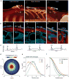
Wireless powering of microdevices in pig abdomen and neck. (a) 3D computed tomography (CT) showing the relative position of the phased surface and the microdevice (white arrow) in the peritoneal cavity of the upper and lower abdomen and the carotid sheath in the neck. Local coordinate axis x (white), y (green), and z (red) of the phased surface is shown. The trajectories of the device are labeled (1), (2), and (3) respectively. Scale bar, 1 cm. (b) CT cross-section images with soft tissue contrast. (c) Pixel values along the dotted lines in (b). PS, phased surface; D, device. (d) Trajectory of the microdevice in the transverse (xy) plane superimposed on the contour plot of the normalized received power in homogenous tissue 4 cm below the phased surface. (e) Received power as a function of position along the trajectory. Solid lines show Gaussian fit curves. (f) Normalized curves showing widths of the Gaussian fit.
Fig. 5
Fig. 5
In-vivo wireless cardiac pacing in pig. (a) Microdevice configured as a cardiac stimulator. Scale bar, 2 mm. (b, c, d) Projection x-ray image of the stimulator (white arrow) inserted by catheter in the left ventricle (LV), right atrium (RA), and right ventricle (RV) of the heart. For each pair, the image on the right shows the phased surface placed on the chest. (e) Electrocardiogram recording during 10-s stimulation and rest cycles. Stimulation pulse width, 10 ms; period, 600 ms (LV), 500 ms (RA), and 400 ms (RV); average power, 216 mW (LV), 34 mW (RA), and 108 mW (RV). (f) Heart rate during stimulation and rest cycles. Dotted lines show the target heart rate.

References

    1. Chandrakasan AP, Verma N, Daly DC. Ultralow-power electronics for biomedical applications. Annu Rev Biomed Eng. 2008;10:247–274. - PubMed
    1. Dagdeviren C, et al. Conformal piezoelectric energy harvesting and storage from motions of the heart, lung, and diaphragm. Proc Natl Acad Sci, USA. 2014;111:1927–1932. - PMC - PubMed
    1. Leonov V. Thermoelectric energy harvesting of human body heat for wearable sensors. IEEE Sensors J. 2013;13:2284–2291.
    1. Schuder J, Stephenson H, Jr, Townsend J. High level electromagnetic energy transfer through a closed chest wall. Inst Radio Engrs Int Conv Record. 1961;9:119–126.
    1. Jow UM, Ghovanloo M. Design and optimization of printed spiral coils for efficient transcutaneous inductive power transmission. IEEE Trans Biomed Circuits Syst. 2008;1:193–202. - PubMed