Review
. 2018 May:64:1-55.
doi: 10.1016/j.preteyeres.2017.11.003. Epub 2017 Dec 8.

Optical coherence tomography angiography

Affiliations
Review

Optical coherence tomography angiography

Richard F Spaide et al. Prog Retin Eye Res. 2018 May.

Abstract

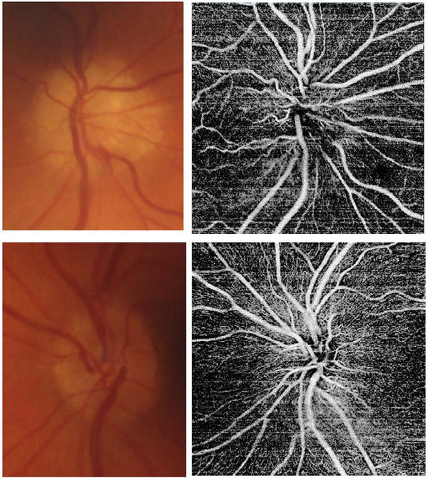
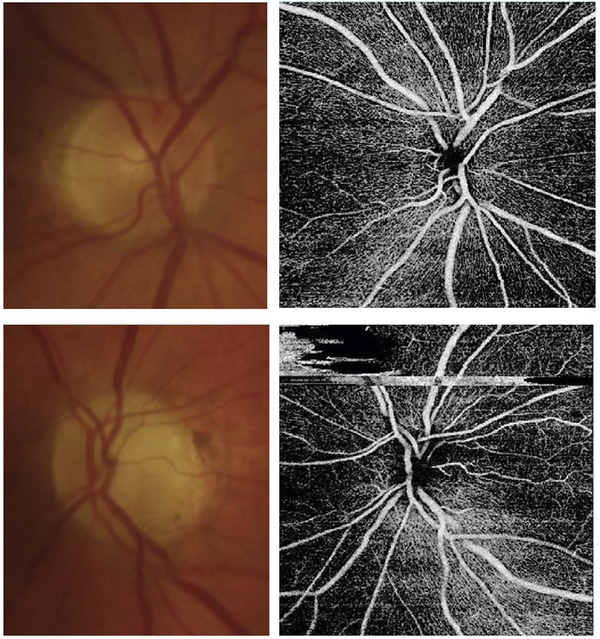
Optical coherence tomography (OCT) was one of the biggest advances in ophthalmic imaging. Building on that platform, OCT angiography (OCTA) provides depth resolved images of blood flow in the retina and choroid with levels of detail far exceeding that obtained with older forms of imaging. This new modality is challenging because of the need for new equipment and processing techniques, current limitations of imaging capability, and rapid advancements in both imaging and in our understanding of the imaging and applicable pathophysiology of the retina and choroid. These factors lead to a steep learning curve, even for those with a working understanding dye-based ocular angiography. All for a method of imaging that is a little more than 10 years old. This review begins with a historical account of the development of OCTA, and the methods used in OCTA, including signal processing, image generation, and display techniques. This forms the basis to understand what OCTA images show as well as how image artifacts arise. The anatomy and imaging of specific vascular layers of the eye are reviewed. The integration of OCTA in multimodal imaging in the evaluation of retinal vascular occlusive diseases, diabetic retinopathy, uveitis, inherited diseases, age-related macular degeneration, and disorders of the optic nerve is presented. OCTA is an exciting, disruptive technology. Its use is rapidly expanding in clinical practice as well as for research into the pathophysiology of diseases of the posterior pole.

Keywords: Multimodal imaging; Optical coherence tomography; Optical coherence tomography angiography.


Figures

Fig. 1.
Fig. 1.
Simplified schematic of how optical coherence tomography angiography (OCTA) works. OCTA visualizes vasculature by detecting motion contrast from moving blood cells. Repeated B-scans (N1, N2, N3) are acquired from the same retinal location (Line L1) and differences or decorrelations between successive B-scans are calculated (Line L2). The decorrelation data is combined into an OCTA cross sectional image (Line 3) and the procedure is repeated at successive positions to generate a volumetric data set. The acquisition time (TS) for each B-scan is determined by the A-scan rate times the number of A-scans per B-scan. The OCT beam is rapidly scanned back to the initial positon during the fly back time (TF) and the B-scan is repeated after a time delay (ΔT), the interscan time determined by the sum of the acquisition and fly back times. Each A-scan which composes a B-scan is also repeated at the interscan time. The interscan time is an important parameter which determines OCTA sensitivity and saturation behavior.
Fig. 2.
Fig. 2.
Detailed flowchart of OCTA processing. Repeated Bscans (block A) are acquired from the same location. The Bscans have noise which is combined with the image (represented by f). Motion contrast is generated by calculating dissimilarity/decorrelation between pairs of B-scans (block B) and an average is generated (block C) to increase the signal to noise. Repeated B-scans (block A) are also averaged to generate an OCT image with increased signal to noise (block D). The OCT image signal (block D) is also measured on a pixel by pixel basis and if the signal is below a threshold, then a mask (block E) is generated. This threshold mask is then used to remove invalid pixels from the OCTA image (block F) which are associated with low or noisy OCT pixels. The masked OCTA image is then displayed. OCTA images are highly dependent on processing details and parameters, however, this information is proprietary in commercial instruments (From Cole et al., 2017).
Fig. 3.
Fig. 3.
Illustration of how blood flow speed and interscan time affect OCTA signal. The transverse width of the OCT beam is shown in yellow. Black squiggly arrows indicate light backscattered from red blood cells. The rows correspond to different blood flow speeds (va, vb, and vc, increasing by factors 2x in this example) and columns correspond to three equally-separated time points of the repeated A-scans (t1, t2, and t3). The time between repeated A-scans is Δtα; the time between the first and third A-scans is Δtβ = 2 × Δtα. The left panels (A.1, B.2, and C.1) are all identical, representing the initial positions of the cells; while subsequent columns show the displaced blood cells (Δd, 2Δd, 4Δd). The graphs under each panel show how the positions of the cells (x) change with repeated A-scans (different colored dots showing different cells). The displacement of the blood cells depends on flow speed and interscan time (displacement = speed × interscan time). Measurements with twice the interscan time Δtβ = 2 × Δtα (i.e., first-to-third column) are equivalent to doubling the blood flow speed for an interscan time Δtα; thus, A.3 is identical to B.2, and B.3 is identical to C.2. When flow is fast vc and the interscan time is long Δtβ, a (purple) cell at the edge of the OCT beam and passes nearly to the other side (C.1 to C.3); this corresponds to the maximum distinguishable speed, or the saturation speed for that interscan time. Conversely, when flow is slow va and interscan time short Δtα, the cell translates very little during the interscan time (A.1 to A.2); this corresponds to the slowest detectable speed for that interscan time. By shortening the interscan time from Δtβ to Δtα (C.3 to C.2), the cell travels half the distance and so the saturation speed is halved and it is possible to distinguish differences in flow; conversely by lengthening the interscan time from Δtα to Δtβ (C.2 to C.3), the cell travels twice the distance and so the slowest detectable speed is halved and sensitivity is improved.
Fig. 4.
Fig. 4.
Sigmodal relationship between flow and OCTA signal. Motion contrast algorithms for OCTA typically have a sigmoidal relationship between flow and OCTA signal. Decorrelation signal (vertical axis) versus flow speed (horizontal) is shown for long (top) and short (bottom) interscan times. Current commercial instruments use long interscan times (top) and have good sensitivity to slow flows (slowest detectable flow). However, faster flows (above the fastest distinguishable flow) have a saturated OCTA signal and cannot be differentiated. If faster interscan times are used (bottom), the sensitivity to slow flow is lost, but faster flows are no longer saturated, enabling the detection of flow impairment. OCTA using slow interscan times (3.0 ms) detect large numbers of vessels, but poorly detect differences in faster flow. OCTA using fast interscan times (1.5 ms) do not detect vessels having slower flow speeds, but detect differences in faster flow. Using variable interscan times it is possible to differentiate flow impairment. The scale bars are 500 μm and the images are enlarged from a 6 mm × 6 mm field of view (Modified from Choi, Ophthalmology 2015).
Fig. 5.
Fig. 5.
Variable interscan time analysis (VISTA) visualization. Example of VISTA visualization of choriocapillaris flow impairment in a 75-year-old GA patient. SS-OCT and OCTA acquired with 400,000 A-scans per second with 6 mm × 6 mm field of view. (A) Fundus photo cropped to OCT field of view. (B) Fundus autofluorescence. (C) OCT en face image, mean projection. (D) OCTA en face image with 1.5 ms interscan time, mean projection through ∼90 μm slab below Bruch’s membrane. (E) OCTA with 3.0 ms interscan time, mean projection through ∼90 μm slab below Bruch’s membrane. Comparing the 3.0 ms–1.5 ms interscan time images shows regions of choriocapillaris flow impairment. (F) VISTA image with red vs blue false color indicate faster vs slow erythrocyte speed. The left margin of the GA exhibits a region of flow impairment (From Ploner et al. Retina, 2016).
Fig. 6.
Fig. 6.
OCTA attenuation artifacts from threshold masking. Valid OCTA information can only be obtained from regions with high OCT signal. Example data from a 78-year-old male GA patient. (A.1) En face OCT, mean projection of the entire retina. (A.2) OCT B-scan at position of dashed black line in en face OCT. (A.3) OCTA thresholded at mean + 2x standard deviation (SD) of the noise in OCT. (A.4) OCTA thresholded at mean + 6x SD of the noise. (A.5) OCTA without thresholding. Rows B-E, 2–5 show en face OCTA images summed between the red contours shown on the OCT B-scan (left column). The columns 2–5 show en face OCTA thresholded at mean + 2x SD, mean + 6x SD, and unthresholded. (1–5b) are enlargements of the dashed white boxes shown in (B–E). OCTA with low threshold has masked regions where the OCT signal is low. Vitreous and sclera appear dark (A.3) and regions within the choriocapillaris appear dark (E.3a and E.3b). OCTA with high thresholds or unthresholded appears bright within the vitreous and sclera, extending below the sclera (A.5). These regions do not have flow, but OCTA decorrelations are generated by noise in the OCT image.
Fig. 7.
Fig. 7.
How retinal capillary plexus and choriocapillaris images are generated. Vascular layers can be independently displayed by segmenting retinal architecture in OCT structural images and projecting the OCTA over axial depth ranges in order to generate en face images. (A) En face OCT image. (B) OCT B-scan through the macula with enlargement (C) showing retinal layers. (D) Retinal layers showing segmentation contours; D1 indicates the ILM; D2 indicates contour C3 offset by half the INL width; D3 indicates the IPL-INL boundary; D4 indicates the midline between contours D3 and D5; D5 indicates the INL-OPL boundary; D6 indicates contour D5 offset by half the INL width; contour D7 indicates the Bruch’s membrane. (E) En face OCTA of the choriocapillaris was generated by projecting a thin slab below Bruch’s membrane D7. (F) En face OCTA of the total retinal vasculature, projecting from the ILM to the RPE (contour not shown). En face OCTA images of different capillary plexuses generated by summing over depth ranges. OCTA of the surficial (G), intermediate (H) and deep plexus (I) were generated by projecting between contours D1 to D2, D2 to D4, and D4 to D6 respectively. (Adapted from Choi et al. Retina, 2017).
Fig. 8.
Fig. 8.
OCTA of the choriocapillaris. Mosaicked OCT and OCTA of the choriocapillaris spanning ∼32 mm across the retina. Imaging performed using an SS OCT with 400,000 A-scans per second. Four repeated horizontal B-scans of 800 A-scans each were acquired over 400 vertical positions on a 3 mm × 3 mm fields. En face OCT retinal images (top row) and OCTA of choriocapillaris (bottom row). OCTA shows that choriocapillaris has densely packed honeycomb structure near macula and sparser, lobular structure towards the periphery. (Adapted from Choi et al., 2013a).
Fig. 9.
Fig. 9.
En face and B-scan visualization of OCTA. OCT, OCTA, and FA, and ICGA images from an 87-year-old with a CNV lesion exhibiting both occult and classic component. (A) En face OCT projection through the entire volume. (B) En face OCTA projection over the retinal vasculature. The dark rectangles are missing data from saccadic eye motion. (C) Early-phase FA. Arrows point to the classic component of the lesion. (D) Early-phase ICGA. Arrows point to the occult component of the lesion. (E) En face OCTA projection through the depths spanned by the lesion. (F) Corresponding en face OCT projection. (G–H) OCT and OCTA B-scans at position of the dashed arrows in E, and F, respectively. (I) Orthoplane visualization, where the OCTA is overlayed red on the OCT. (J) B-scan at the plane indicated with the solid arrow in (I). (K) B-scan at the plane indicated by the dashed arrow in the (I). (L) En face image at the plane indicated by the intersecting arrows in (L). Orthoplane visualization can reduce the risk of misinterpretation.
Fig. 10.
Fig. 10.
Graphic user interfaces in commercial instruments. Representative screenshots from commercial OCTA instruments, including the Optovue (top left), Zeiss (top right) and Topcon (bottom) OCTA displays. Commercial displays and user interfaces enable segmentation of retinal layers as well as simultaneous viewing of OCT and OCTA data. Many commercial instruments use false coloring to differentiate depths of vasculature or different retinal capillary plexuses. At the time of this writing, commercial software is still rapidly evolving. The challenge will be to achieve consistent notation and quantitative measurements between instruments from different manufacturers.
Fig. 11.
Fig. 11.
This 64 year-old male with MacTel2 had a visual acuity of 20/30 in each eye and was imaged with volume rendered OCTA with segmentation of the retinal cavitations from the structural OCT data. There are prominent right-angle veins in each eye. (A) The exit point of the right-angle vein from the substance of the retina in the right eye is at the nexus of a network of vessels, which appear to be drawn into a central focus. Retinal arterioles, venules, and small order vessels appear to be involved. The foveal avascular zone is distorted and appears to be pulled toward the temporal macula. There is a group of neighboring (and in the image, overlapping) foveal cavitations (cyan) that are on the temporal side of the foveal avascular zone. (B) Viewed from the choroidal side, the deeper penetrating vessels appear as yellow. This region corresponded to the area of late fluorescein staining. (C) More prominent traction on the vessels are evident in the left eye with pulling of the perifoveal vessels into an apex of a triangle (open arrow). (D) Viewed from the choroidal side the vessels deep to the deep vascular plexus are shown in yellow. The cystoid space in the left eye (cyan) has a complex outer boundary (From Spaide et al. Retina, 2017).
Fig. 12.
Fig. 12.
(A) Mactel2 in a 58-year-old with right-angle veins and cavitations imaged with volume rendered OCTA with segmentation of the retinal cavitations from the structural OCT data. The foveal avascular zone is smaller and displaced toward the central focus of the vascular lesion in the temporal macula. Note the vessels of the perifoveal ring are drawn toward the center of the vascular aggregate and for angular figures and their apices (one of which is shown by the open arrow) point toward the center of the vascular aggregate (Modified from Spaide et al. Retina, 2017). (B) A vector field map showing the retinal displacement over a 10 year period. The tissue displacement reveals an epicenter in the temporal juxtafoveal macula. (C) A color-coded volume rendering with the superficial vessels shown in blue, the deep plexus red, the vessels deeper than the deep plexus (as occurs in MacTel2), yellow and vessels below the level of the RPE, green. (D) When viewed from the choroid, the proliferating vessels under the RPE have an enlarged saccular nature, which is different from the vessels in the overlying layers.
Fig. 13.
Fig. 13.
The effects of imaging wavelength on image penetration and attenuation artifacts. (A) OCT images from a spectral domain SD-OCT instrument operating at 840 nm wavelength compared with (C) images form a swept source SS-OCT instrument at 1050 nm. The en face OCT images (A.1 and C.1) are from the depth ranges shown in the respective cross-sectional images (A.2, A.3 and C.2, C3). B-scans at 840 nm (A.2 and A.3) exhibit more attention below the retina and drusen than B-scans at 1050 nm (C.2 and C.3). OCTA images at 840 nm wavelength and 1050 nm are shown in (B) and (D) respectively. The OCTA images represent the choriocapillaris and are from depth ranges shown in the respective cross-sectional images (A.2, A.3 and C.2, C.3). Drusen produce OCT signal attention for structures below them. The attenuation is appreciable for 840 nm as seen in the en face (A.1) and cross-sectional images (A.2, A.3) and corresponding regions of the OCTA (C) do not have valid OCTA signal. Attenuation is less at 1050 nm as seen in the en face (C.1) and cross-sectional images (C.2, C.3) and corresponding regions of the OCTA (D) show the presence of signal. Projection artifacts from retinal vasculature are observed OCTA images at both wavelengths.
Fig. 14.
Fig. 14.
Schematic showing how software motion correction works. Software motion correction can estimate and compensate for eye motion on a per A-scan basis in all three dimensions. Two volumes with perpendicular raster scans are acquired (XFast vs YFast raster directions). These two volumes will have motion distortion in different directions. Displacements are estimated for all A-scans in each of the volumes with the objective of generating undistorted, motion corrected volumes. The two volumes are assumed to be motion corrected if they are similar. The A-scan displacements are calculated using iterative, multi-resolution techniques with a nonlinear optimizer and the resulting motion corrected volumes are merged or averaged to increase the signal to noise. Unlike eye tracking, software methods can correct motion in all three dimensions and can be implemented on different instruments since they do not require hardware modifications.
Fig. 15.
Fig. 15.
Example of software motion correction and artifacts. Effect of patient eye motion and software motion correction on en face OCT and OCTA data. Data is from an 87-year-old patient with a CNV lesion exhibiting both occult and classic components. (A) En face projection of the Yfast OCT volume through the depths spanned by the lesion. (B) En face projection of the X-fast volume through the depths spanned by the lesion. (C) En face projection of the motion corrected and merged OCT volumes (A) and (B), with the projection is taken through the depths spanned by the lesion. (D–F) OCTA volumes corresponding to (A–C), respectively. The image data (C, F, I) is motion corrected in all three dimensions and signal to noise is improved. However, there are regions where data is missing due to eye motion. These are evident as rectangular gaps in the en face OCTA image (I)
Fig. 16.
Fig. 16.
Combined software motion correction and eye tracking. Top row shows software motion correction only, bottom row shows eye tracking and software motion correction. En face OCTA with perpendicular raster scans (A) and (B) have discontinuities from eye motion. Eye tracking reduces the effects of eye motion in (E) and (F). Reducing motion in the initial data improves the results of software motion correction (G, H) compared with software motion correct without eye tracking (C, D). Eye tracking enables longer data acquisition times and large data sets, while also avoiding gaps in data which can occur with software motion correct alone.
Fig. 17.
Fig. 17.
OCTA artifacts from lipid deposits. OCTA decorrelation artifacts generated by intraretinal lipid in a patient with radiation retinopathy affecting the peripapillary retina. (A) There is an area of edema ringed by lipoprotein precipitates in this color image taken a few months prior to OCTA imaging. (B) OCTA projection, segmented at Henle’s fiber layer which is normally an avascular area. Note the lipid generates a high decorrelation signal. (C) Segmented, albeit somewhat inaccurately at the deep vascular plexus, there are artifacts from the lipid as well (arrowheads). (D) Note that even at this level, the false color flow density map shows the lipid as high flow regions (arrowheads). Lipoprotein precipitates generate motion contrast, which resemble blood flow on OCTA.
Fig. 18.
Fig. 18.
Schematic showing how changes in axial position of a reflective structure, such as a lipoprotein granule, could cause subtle changes in the intensity of the detected reflection. This could cause a decorrelation, which would incorrectly be rendered as a flow signal. Similar changes in reflectivity could occur with transverse motion.
Fig. 19.
Fig. 19.
OCTA artifacts from cystoid macular edema. OCTA decorrelation artifacts can be generated by the walls around cystoid spaces. (A) OCTA artifact in an eye with diabetic cystoid macular edema (arrow). There are no blood vessels in the wall of the cystoid space. (B) The false color flow density map shows a low level of flow in the corresponding area (arrow) although no flow is present. These structures exhibit small displacements between repeated B-scans, generating false OCTA signals.
Fig. 20.
Fig. 20.
Demonstration showing how OCTA projection artifacts are generated. (A–C) Water is flowing in the clear channel and in repeated images over time, are seen as a region of variable reflections. However, the light transmitted through the water illuminates the background and the illumination also changes over time. The variance (D) of the images can be computed to show motion contrast. The changing background illumination is detected even though the background itself is not moving. Similarly, flowing blood cells can generate motion contrast for stationary structures which are below them. (From Spaide et al., 2015a).
Fig. 21.
Fig. 21.
Projection artifacts in OCTA. (A) The inner vascular plexus is shown in an en face OCTA image (top), along with a B-scan and flow overlay (bottom). (B) An en face OCTA at the level of the RPE exhibits a flow signal that looks like the inner vascular plexus. The B-scan with flow overlay and an enlarged inset are shown (bottom). The vessels with flow in the inner plexus produce projection artifacts in the RPE and subretinal structures which are stationary (arrows).
Fig. 22.
Fig. 22.
Projection artifact removal. The en face OCTA image in (A) is at the level of the choriocapillaris, but exhibits projection artifacts from the retinal circulation. These projection artifacts can make interpretation difficult because vascular features can appear in structures without vasculature. (B) The OCTA signal from the retinal circulation was used to remove the projection artifact from the en face OCTA image of the choriocapillaris. Manufacturers have implemented different algorithms to reduce or remove projection artifacts.
Fig. 23.
Fig. 23.
Segmentation errors. Example showing segmentation error in a patient with high myopia. The en face OCTA image (top) shows blood vessels of many different sizes. The upper left does not appear to show any flow. (Bottom) The segmentation contours, shown in a B-scan with a flow overlay, exhibits serious errors. The segmentation contour was intended to be the choriocapillaris but deviates into the choroid, sclera and is outside of the eye entirely (left side). This produces the black area in the upper left corner of the en face OCTA image because the image contains information from the wrong depth. Segmentation errors can cause severe errors in interpretation. The risk of errors can be reduced by viewing cross sectional images to confirm the integrity of the en face projection images.
Fig. 24.
Fig. 24.
Fundus photos of the left eye of a patient with advanced non-neovascular age-related macular degeneration and geographic atrophy (GA). A. Image with a typical flash white-light fundus camera system (Kowa VX-20). Note natural appearance of the retinal blood vessels and drusen. The borders of the GA are difficult to discern. Confocal white light (B, Centervue Eidon) and multicolor (C, Heidelberg Spectralis) of the same eye. The appearance of the color is different, especially for the multicolor image, but the borders of the atrophy are easier to discern with the confocal systems.
Fig. 25.
Fig. 25.
Fundus autofluorescence (AF) imaging. A. Blue-light scanning laser ophthalmoscope FAF image of a normal right eye. Retinal blood vessels are dark and seen in sharp contrast as they block the AF from the retinal pigment epithelium (RPE). The optic nerve head is similarly dark due to the absence of RPE at this location. In addition, as blue light is absorbed by the macular pigment, the central macula (fovea) is also relatively hypo-autofluorescent. B. FAF image of the eye of a patient with Best’s vitelliform macular dystrophy. The vitelliform lesion is intensely autofluroescent. Blue-light scanning laser ophthalmoscope (C) and green-light flash fundus camera (D) FAF imaging of a patient with geographic atrophy (GA). The high contrast of FAF imaging, with absence of the AF in the region of photoreceptor and RPE loss allows the borders of the atrophy to be precisely defined.
Fig. 26.
Fig. 26.
(A) Flourescein angiogram of the macula of a normal eye using a confocal scanning laser ophthalmoscopic system. The parafoveal capillaries and the foveal avascular zone may be discerned, but the capillary circulation outside this region are not evident. (B) Fluorecein angiographic image of an eye with a classic choroidal neo-vascularization (CNV). Although hyperfluroescence from the vascular lesion is evident, the microvascular network of the CNV lesion is not apparent. Leakage of dye, however, is evident. (C) Widefield fluorescein angiographic image (Optos 200Tx) of an eye with diabetic retinopathy. The eripheral non-perfusion temporally can be recognized by the absence of the large vessels and the feature-less appearance of the retina. The capillary circulation outside of the central macula is not evident. Multiple small areas of retinal neovascularization are identified by the hyperfluorescent leakage of dye, but the fine vessels of the neovascular tufts cannot be seen.
Fig. 27.
Fig. 27.
(A) Swept source OCT (Topcon Triton OCT) B-scan of the macula and optic nerve of a normal eye. The choroid and lamina cribosa of the optic nerve are well-seen as are the various layers of the neural retina. The hyper-reflective oval profiles of the large vessels of the optic nerve head are also evident. (B) En face OCT from a dense swept source OCT acquisition (1024 × 1024 A-scans). Though the retinal vessels are well-seen, even at this “megapixel” resolution, the retinal capillaries cannot be visualized.
Fig. 28.
Fig. 28.
Swept source OCT B-scan (Topcon Trion OCT) of a paramacular region of a normal eye. The approximate vertical dimensions of the various vascular layers are shown with colored calipers: what is referred to as the choriocapillaris (yellow), Sattler’s layer of medium-sized vessels (green), Haller’s layer of large-sized vessels (blue). Note, no clear demarcation can be discerned between these various layers and the depth of the choriocapillaris is much less in life than what is commonly depicted in OCT sections.
Fig. 29.
Fig. 29.
Swept source montage OCT-Angiogram illustrating the superficial capillary circulation of the macular and peripapillary retina. Whereas the central macular circulation is oriented in a more circular fashion around the foveal avascular zone, the superficial peripapillary capillaries have a distinct radial orientation resembling the orientation of the retina nerve fiber layer.
Fig. 30.
Fig. 30.
Optical coherence tomography angiography shows four morphologically varied retinal capillary networks along the maculo-papillary axis. A radial peripapillary capillary plexus is located in the nerve fiber layer slab (A). The superficial vascular plexus slab is found in the ganglion cell layer, and is segmented as the inner 80% of the ganglion cell complex, excluding the nerve fiber layer (B). The intermediate capillary plexus is segmented between the outer 20% of the ganglion cell complex to the inner of the inner nuclear layer (C). Finally, the deep capillary plexus is segmented between the outer 50% of the inner nuclear layer and the outer plexiform layer (D).
Fig. 31.
Fig. 31.
Macular OCT angiograms (full retinal thickness) from one eye of six normal subjects. Note considerable variation in the size and shape of the foveal avascular zone (FAZ). OCT = optical coherence tomography.
Fig. 32.
Fig. 32.
Choriocapillaris images from subjects of varying ages obtained using optical coherence tomography angiography of the central macula. Each image represents an area of 3000 × 3000 μm. The bright areas correspond to high flow signal while the dark regions are called flow voids and represent areas where there is a lack of flow signal. The age range is from 27 years (upper left) to 88 years (lower right). The bottom row of images shows not only those of increasing age, but also with choroidal neovascularization in the fellow eye. Reprinted from Spaide (2016a).
Fig. 33.
Fig. 33.
Number and sizes of the thresholded flow voids of a representative eye. (A) The distribution of the number of flow voids versus linearly binned sizes shows a high amount of skew with a long tail. (B) The probability density function shown in a log-log plot is nearly linear, demonstrating the power law characteristics. Because of the finite size of the image and the imaging of deeper vessels that have a looser packing density the actual relationship was hypothesized to be a truncated power law, which was confirmed by maximal likelihood methods. (C) The log number versus log size of the flow voids is shown in a log-log plot with logarithmic binning showing the linear relationship characteristic of a power law. Reprinted from Spaide (2016a).
Fig. 34.
Fig. 34.
In a log-log plot the data follows a y = mx + b slope intercept relationship and provides parameters that can be evaluated using statistical analysis. The significant predictors of slope were age and hypertension; increasing age and the diagnosis of hypertension were both associated with decreasing slope. The parameter b represents the offset, which is decreased by increasing age, the diagnosis of hypertension, and the presence of late age related macular degeneration (AMD) in the fellow eye. Flow voids having larger regions, as would be shown along the right side of the slope, are more likely to occur in older patients, those with pseudodrusen, and in association with late AMD in the fellow eye. Reprinted from Spaide (2016a).
Fig. 35.
Fig. 35.
Potential explanation for observed flow patterns in the choriocapillaris. (A) The choriocapillaris is a dense mesh of capillaries as shown in red and in the posterior pole the intercapillary pillars are small (shown in black). (B) The presence of ghost segments (white arrow) occurs with age, but is more common in eyes with drusen and with pseudodrusen. (C) The induced flow abnormality is larger than the segment and is shown in as the blue gradient. (D) To produce a power law relationship, two features need to be present. Additional segments need to become nonfunctional over time and the location of these nonfunctioning segments should have a tendency to occur in the vicinity of an already nonfunctional segment. Reprinted from Spaide (2016a).
Fig. 36.
Fig. 36.
An OCTA image of the submacular choroid obtained in a patient with geographic atrophy. There is atrophy to the right of the dashed yellow line. The larger choroidal vessels show visible flow signal while they do not in the areas with extant retinal pigment epithelium. Note the course of one large choroidal vessel from an area under the RPE (open arrow) to the area of atrophy (white arrow.).
Fig. 37.
Fig. 37.
Swept source OCT angiogram (OCTA) of the macular choroid of a normal eye. The upper panels show the slab en face OCTA image through the vascular layer of interest. The lower panels demonstrate the slab (blue-lines) location of the en face image on a corresponding B-scan. The en face OCTA is shown at the level of the choriocaillaris (left panel), presumed Sattler’s layer (middle), and presumed Haller’s layer (right). The choriocapillaris has a granular texture, but the individual capillaries are not seen. Also, it is important to note that Sattler and Haller layers as histologically defined do not have precise borders or a precise axial position relative to the RPE, and hence these slabs represent approximations. The larger choroidal vessels appear dark, presumably due to loss of signal with depth, projection artifact and decorrelation from overlying retinal vessels and choriocapillaris, and image processing or thresholding artifact.
Fig. 38.
Fig. 38.
Fluorescein angiography (FA) of a diabetic eye (A) and the corresponding OCTA image segmented at the superficial retinal capillary plexus (B) and the deep capillary plexus (C). Note the microvascular changes seen on the OCTA including microaneurysms, vascular dropout and a ragged appearance of the foveal avascular zone. Figure D is the FA cropped to a 3 × 3mm size to correspond to the OCTA image. Blue circles show microaneurysms visualized better on the superficial capillary layer of the OCTA and yellow circles show some examples of microaneurysms visualized better on the deep retinal capillary layer of the OCTA. The red circle demonstrates a microvascular abnormality that spans both the superficial and the deep plexi. Note that there are some microaneurysms that are seen on the FA but not seen on the OCTA. Figure E is a corresponding image of the choriocapillaris showing areas of choriocapillaris dropout.
Fig. 39.
Fig. 39.
This is an overlay of the OCTA of diabetic microaneurysms with the size of the microaneurysm as measured on the structural OCT scan. The superficial vascular plexus flow is shown in red while the structural OCT information is shown in green. Signal common to both is yellow. Note the microaneurysms visible centrally have yellow cores with a relatively thick wall. Microaneurysms may have thrombi and regions of slow flow that may be below the detection threshold of OCTA.
40.
40.
Neovascularization of the disc is seen in this OCTA image projecting into the vitreous space (A). 4 and 8 weeks after treatment with anti-VEGF injections, the pre-retinal neovascularization is seen to regress (B and C panel respectively).
Fig. 41.
Fig. 41.
Volume rendered optical coherence tomography angiography of the right eye with areas of absent flow signal. (A) There is attenuation of vascular flow density in the inferior temporal macula of the inner vascular plexus. The double white arrow shows the extent of absence of underlying flow signal from the underlying deep plexus. (B) The opacity of the inner vascular layer was reduced to allow visualization of the deep plexus. Note the absence of flow signal inferotemporally. (C) The structural optical coherence tomography image used to derive the flow data. The double white arrow is scaled to show the same lateral extent as the double white arrow in the picture in the upper left. There is absence of laminar detail associated with retinal thinning, which is consistent with the entity disorganization of retinal inner layers (DRIL). Note the inner nuclear layer is not clearly visible and as such more than the inner retinal layers are involved. Reprinted from Spaide (2015c).
Fig. 42.
Fig. 42.
Images of a patient with diabetic macular edema. (A) FA early frame (A1) and late frame (A2) showing that some microaneurysms are leaking while others are not. This is somewhat difficult to identify because of previous focal laser. B1 is a magnified FA image. The 3 mm × 3 mm OCT angiogram is overlaid on the FA image (B2) to show which microaneurysms on the OCT angiogram correspond to those on the FA. Note that not all microaneurysms seen on the FA are seen on the OCTA. (B3) The OCT thickness map is superimposed over the OCTA image to show that there is thickening due to leakage at and around some microaneurysms, while the non-leaking microaneurysms do not show any fluid accumulation. (C1-C3) OCT b-scan, OCT thickness map and OCTA image from the same patient visit in A-B showing edema. (D1–3) OCT b-scan, thickness map and OCTA from the same patient in A-B after intravitreal injections of anti-vascular endothelial growth factor agents. The edema has improved.
Fig. 43.
Fig. 43.
Müller cell schematic. (A) Müller cells traverse most of the thickness of the retina and are the major determinant of retinal fluid movement. Müller cells extend from the inner retina to the inner segments of the photoreceptors, where they form junctional bonds with the photoreceptors. This establishes a boundary at the outer border of the retina that has limited permeability to the passage of water. (B) The footplates of the Müller cells form the internal limiting membrane of the retina. At the inner border of the Müller cell there are highly concentrated aggregates of aquaporin 4 channels (schematically shown as blue rectangles) that colocalize with potassium channels (not shown). There are aquaporin channels scattered over the surface of the Müller cell, but at a much lower frequency. (C) Müller cell processes surround the retinal vessels of the inner and deep vascular layers. The appositional surface has densely packed aquaporin 4 channels along with potassium transport channels (not shown). Reprinted from Spaide (2016b).
Fig. 44.
Fig. 44.
Schematic drawing of the retina highlighting the Müller cells, which can buffer both K+ ions and water (double arrows), which move in tandem. Reprinted from Spaide (2016b).
Fig. 45.
Fig. 45.
Excessive water, potassium, or both may be transported to the vitreous or to the superficial or deep plexus via potassium pumps and aquaporin 4 channels. The spatial buffering of potassium by this mechanism and that shown in Figure is called the potassium siphon.
Fig. 46.
Fig. 46.
Varying sized flow voids in the deep vascular plexus in eyes with diabetic macular edema. (A) The cystoid spaces (in teal) are integrated into the volume rendered vascular structure. The cystoid spaces are located below the superficial vascular plexus. (B) The data set was rotated to show the view of the retina from below. The structure of the cystoid spaces is evident and there is a loss of flow signal from the deep vascular layer larger in extent than the cystoid spaces. (C) The imaging data from the cystoid spaces was not shown. The absence of the deep plexus under some areas of the superficial vascular plexus can be seen. (D) With the dataset rotated so the deep plexus is on top, the group of larger cystoid spaces is seen to correlate to a region in which the deep plexus flow data is not apparent. The smaller region of edema has an even smaller flow void (arrow). Reprinted from Spaide (2016b).
Fig. 47.
Fig. 47.
Volume rendered angiographic and structural optical coherence tomography of central retinal vein occlusion. (A) View of the retina from the vitreous side; the superficial plexus is blue, the deep plexus red, and the cystoid spaces are cyan. Note the decreased vascular density overlying areas of cystoid edema. (B) When viewed from the underside of the retina the extent of the cystoid spaces is easier to visualize. (C) After an intravitreal injection of ranibizumab the cystoid edema has temporarily resolved. The vascular abnormalities in both the superficial vascular plexus and deep plexus show significant abnormalities. (D) There are several subtle aspects in the macular regions. Thinning of the macula allows some of the superficial vessels to be at the same level of the surrounding deep plexus. These vessels can have segments that are red (open arrowheads). Small particulate areas of decorrelation (white arrow) likely represent protein or lipoprotein aggregates. Larger collections are also present (yellow arrow). Note the small and large particles are not vessels because they are spherical, don’t connect to any other structure, and don’t necessarily have sizes corresponding to the surrounding vessels. Modified from Spaide (2016b).
Fig. 48.
Fig. 48.
The patient had a recurrence of edema visible from the top (A) and bottom (B) of the retina. Note the similarity in the distribution of cystoid spaces to that seen in Fig. 47. Note the particulate dots of decorrelation that are not attached to any vascular structure. Reprinted from Spaide (2016b).
Fig. 49.
Fig. 49.
Volume rendered angiographic and structural optical coherence tomography of an eye with a branch retinal vein occlusion. (A) The superficial vascular plexus is shown in blue, the deep in red. The cystoid spaces were derived from the matched structural optical coherence tomography scan and are shown in cyan. Some of the deep vascular plexus is seen above the cystoid spaces (open arrows). (B) The cystoid spaces are easier to visualize when the imaged is flipped about the vertical axis. Note the extent and distribution of the cystoid spaces.
Fig. 50.
Fig. 50.
Fluid is potentially removed from the retina by action of the Müller cells and the deep vascular plexus. There is no functional mechanism to clear excess fluid through the deep plexus if that layer has no flow. Reprinted from Spaide (2016b).
Fig. 51.
Fig. 51.
Without a mechanism to evacuate excess fluid, cystoid spaces are created. Reprinted from Spaide (2016b).
Fig. 52.
Fig. 52.
Choriocapillaris loss under drusen. A1 is the intensity B scan image and A2 is a magnified view of the druse in A1 showing good penetration of light under the druse (i.e. no shadowing). B1 is the angiographic image and B2 is a magnified angiographic image. Note the loss of choriocapillaris flow on the OCTA image noted under the druse (yellow arrow).
Fig. 53.
Fig. 53.
A. structural OCT B-scan. The black arrow shows choroidal Haller layer vessel not penetrated by the light. White arrows show choroidal Haller layer vessel penetrated by the light. Dotted line shows the separation between the area with and without RPE. Asterisk shows the effect of the projection artifact of the choriocapillaris B: OCTA B-scan. Stars identify area without choriocapillaris. C: OCTA en face image of the same region sampled at the level of the Haller layer as shown by the red lines.
Fig. 54.
Fig. 54.
Choriocapillaris loss under geographic atrophy. This figure shows a color fundus photo (A) and a fundus autofluorescence image (B) of a patient with geographic atrophy (GA). The area of GA is outlined. Image C is an OCTA of the choriocapillaris slab underlying the area of GA outlined in yellow. Loss of choriocapillaris can be seen, and the larger choroidal vessels are seen occupying the space that would ordinarily be occupied by the choriocapillaris. Also note that there appears to be some CC thinning in some of the areas surrounding the area of atrophy.
Fig. 55.
Fig. 55.
Semi-quantitative OCT angiography using variable interscan time analysis in a patient with geographic atrophy. Red represents fast flow and blue represents slow flow. Note that there is both choriocapillaris loss and slowing of flow underlying the area of geographic atrophy. Surrounding the area of atrophy, some areas have vessels with slower flow (between arrows) while other areas do not have slowing of flow.
Fig. 56.
Fig. 56.
En face OCTA (A) and B scan with flow overlay (B) of a patient with type 1 macular neovascularization (MNV). The B scan shows a pigment epithelial detachment with flow noted within the pigment epithelial detachment (white arrows).
Fig. 57.
Fig. 57.
A type 3 (A1-A3) and mixed type 1 and 2 (B1-B3) MNV is seen. A1 is a fluorescein angiogram showing the type 3 lesion. On OCTA, the feeder vessel (A2) that extends from the retina through the break in the RPE (arrowhead A3) and into the pigment epithelial detachment is seen. B1-B3 demonstrate a mixed type 1 and 2 MNV with a type 1 component seen on choriocapillaris segmentation (B2) and a type 1 component seen on outer retinal segmentation. Note the trunk vessel centrally and the arborizing network of vessels around it.
Fig. 58.
Fig. 58.
This shows the acute response of MNV 1 month following an injection of antiVEGF agents. A1, B1 and C1 represent pre-injection MNV while A2-C2 represent the corresponding MNVs one month post injection of anti-VEGF agents. The overall size of the MNV shrinks, best noted in A2. The density of the vasculature within the MNV is seen to decrease as are the finer vessels that occupy the margins of the MNV (B2 and C2). Meanwhile, the larger vessels may become larger and occupy more of the lesion. Also note the choriocapillaris loss surrounding the MNV.
Fig. 59.
Fig. 59.
Artefactual appearance of MNV as a result of atrophy. A loss of the choriocapillaris as a result of atrophy (demarcate by the arrows in B) and the resultant superficial migration of the larger choroidal vessels into the area normally occupied by the choriocapillaris gives the appearance of an MNV (A) when segmentation is performed at the choriocapillaris level (red line).
Fig. 60.
Fig. 60.
Variable interscan time analysis for blood flow speed shows high speeds of flow approximating that of the larger retinal vessels in the larger trunk vessels of the MNV (seen in red) and slower flow speeds (yellow and blue) in the smaller vessels and in the marginal vessels of the MNV.
Fig. 61.
Fig. 61.
Multimodal imaging of a patients with myopic choroidal neovascularization. MultiColor imaging of a patient with pathologic myopia shows white areas of focal chorioretinal atrophy (A). Blue light fundus AF shows a hypoautofluorescent area (B). Early phase of indocyanine green angiography (ICGA) (C) and FA (FA) (E) reveal an hyperfluorescence area that become more intense with moderate leakage in the late phase (D and F, respectively), as type II classic active choroidal neovascularization. En face OCT angiography section (G) just below retinal pigment epithelium (H) shows type II neovascular network with well circumscribed appearance.
Fig. 62.
Fig. 62.
Multimodal imaging of a patient with angioid streak complicated by choroidal neovascularization. ICGA (A) and FA (B) reveal the light hyperfluorescence corresponding to the angioid streak as the results of the rupture of Bruch’s membrane and the hyperfluorescence of the choroidal neovascularization. Infrared reflectance (C) displays the angioid streaks as linear hyporeflective area starting from optic nerve head. Optical coherence tomography angiography (D) shows macular neovascularization with a network that closely followed the trajectory of angioid streak.
Fig. 63.
Fig. 63.
Vascular occlusion in retinal vasculitis with subsequent retinal neovascularization. (A) The most salient feature of the fluorescein angiogram is the area of intense hyperfluorescence from retinal neovascularization (arrow). Temporal and inferior to this are areas seemingly devoid of smaller branch vessels. (B) The OCT angiogram at the level of the retina shows blunted branch vessels and regions of non-perfusion (asterisk). (C) More pronounced pruning is evident with multiple areas of non-perfusion (asterisks). (D) OCT angiography set above the level of the retina shows the retinal neovascularization.
Fig. 64.
Fig. 64.
A 49-year-old HLA-B27 + woman with ankylosing spondylitis. (A) There is subtle sheathing of the vein in the superotemporal arcade (yellow arrowheads), and areas of focal caliber changes (highlighted by white arrowhead). (B) FA shows perivascular leakage and staining extending variable distances from this vein as well as other vessels. The fellow eye showed widespread leakage and staining around larger vessels as well.
Fig. 65.
Fig. 65.
Optical coherence tomography (OCT) findings of perivascular infiltration before and after treatment. Along each row of images, the left panel shows an infrared scanning laser ophthalmoscopic image showing the scan location, the middle panel shows the entire OCT scan, and the right panel shows a highlighted area as demarcated by the white rectangle in the middle panel. (A) Horizontal OCT section through an involved segment of the superotemporal arcade vein. There is an annular zone of increased perivascular reflectivity (arrowheads) around a vein (arrow). Adjacent to this is a region of loss of the laminations of the retina (double arrow). Contained within this region is a zone of increased reflectivity of the inner nuclear layer. It is possible this could be called paracentral acute middle maculopathy, but this term ignores the associated changes in other layers of the retina and the area imaged is not within the anatomic macula. (B) A scan perpendicular to that shown in (A) shows the variable thickening of the retina in the region of loss of laminations. Note the focal area of thinning (blue arrow). The choroid shows increased reflectivity and a loss of visible structure. (C) One week after intravitreal triamcinolone the retina shows thinning in the region of the double arrow. The perivascular reflectivity is thinner (arrowheads) around the retinal vein (arrow). (D) An OCT scan taken perpendicular to (C) shows the thinning
Fig. 66.
Fig. 66.
OCT angiograms of affected area in the patient shown in Fig. 64 and 65. (A) The green line corresponds to the OCT sections shown in Fig. 65. Note the poor perfusion, particularly to the right side of the vein. (B) One week after intravitreal triamcinolone the perfusion showed no significant change. Reprinted from Spaide (2017c). as compared with (B). Note the decrease in the choroidal reflectivity with enhanced visualization of choroidal details (open arrowhead). Reprinted from Spaide (2017c).
Fig. 67.
Fig. 67.
One month after intravitreal triamcinolone. (A) Left panel shows the location of the scan, which is the same as Fig. 65 B and D. The right panel shows continued retinal thinning. (B) Enlarged depiction of the area enclosed by the rectangle in (B). (C) A heat map of the change in retinal thickness from prior to intravitreal triamcinolone. The area of retinal thinning as shown by the heat map is similar to the region of fluorescein leakage and staining seen in Fig. 64 B. Reprinted from Spaide (2017c).
Fig. 68.
Fig. 68.
Comparison of presumed inflammatory versus neovascular lesions in multifocal choroiditis and panuveitis. The left column of images shows a conical infiltration of material that is relatively homogenous and has no demonstrable flow. The lesions in the right column show greater heterogeneity, structure, and contain flow signal.
Fig. 69.
Fig. 69.
Multifocal choroiditis with chorioretinal scars in a patient previously treated with intravitreal anti-VEGF injections. (A) The patient has 2 visible chorioretinal scars and myopic disc changes. (B) The fluorescein shows late staining around the lesion in the fovea. (C) OCT angiography shows a vessel complex most prominently seen at the superior border of the lesion. (D) B-scan with flow overlay shows a tumefaction containing discrete areas of flow signal, consistent with persistent choroidal neovascularization.
Fig. 70.
Fig. 70.
New onset multifocal choroiditis complicated by choroidal neovascularization. A, B, C successive sections showing widespread infiltration of the outer retina with loss of the ellipsoid layer. (D) The OCT angiogram shows discrete areas of CNV, implying the more diffuse deposit is composed of inflammatory collections, exudation from the CNV, or a mixture of both.
Fig. 71.
Fig. 71.
New onset multifocal choroiditis and panuveitis with CNV. (A) This highly myopic patient was seen for her yearly examination. In the past she had surgical repair of a retinal detachment. (B) When seen a year later she had multiple chorioretinal punched out lesions, one of which was ringed by pigment (arrow). (C) FA shows some staining of the pigmented lesion in (B). The depigmented lesions show modest staining. (D) En-face view of OCT angiography shows a lesion containing vessels at the location of the pigmented lesion (arrow). (E) B-scan with flow overlay shows an elevated lesion with internal flow signals that are not projection artifacts from the overlying retina. Because the lesion was pigmented and showed no exudation, the eye was observed with no treatment
Fig. 72.
Fig. 72.
Multimodal imaging of patient with Best vitelliform macular dystrophy. Fundus AF (A) and infrared reflectance (B) show central mixed hyper/hypoautofluorescent lesion with mixed hyper-reflective and hyporeflective material. FA (C) and ICGA (D) reveal a round hypofluorescence area with central hyperfluorescence as window defect and staining, but no leakage. Spectral domain optical coherence tomography (E) shows a flattened lesion by the resorption of the majority of fluid, between retinal pigment epithelium (RPE)/Bruch’s membrane and the ellipsoid zone of the photoreceptors with subtle elevation of the RPE. Optical coherence tomography angiography shows the displacement of blood vessels at both the superficial (F) and deep capillary plexuses of the retina (G). Choriocapillaris (H) reveals a choroidal neovascularization (arrow) vascular network, while choroid segmentation (I) shows a well-defined, large circular area corresponding to the limits of the retinal elevation due to limitation of light penetration.
Fig. 73.
Fig. 73.
Optical coherence tomography angiography (A), fundus AF (B), FA (C) and ICGA (D) of a patient with Stargardt disease. Optical coherence tomography angiography shows no residual choriocapillaris inside the areas of atrophy where large choroidal vessels are clearly visible. Outside these regions, choriocapillaris lobules appear normal in density (A). Fundus AF (B) reveals a large hypoautofluorescent area due to the loss of the retinal pigment epithelium. FA (C) and ICGA reveal the hypofluorescence area, confirming the absence of choriocapillaris.
Fig. 74.
Fig. 74.
Optical coherence tomography angiography of a patient with retinitis pigmentosa. Image of the fundus (A) and blue light fundus AF (B) of a patient with retinitis pigmentosa. OCTA shows narrowed vessels with a progressive vascular rarefaction, from the papilla towards the periphery at the superficial and deep capillary plexuses (C and D, respectively). No vascular abnormalities were detectable at the choriocapillaris and choroid segmentation (E and F, respectively).
Fig. 75.
Fig. 75.
Retinal nerve fiber layer and radial peripapillary capillary changes in glaucoma. Left panel. Anarcuate visual field defect is present. Middle panel, the retinal nerve fiberlayer analysis shows a region of inferotemporal retinal nerve fiber layer thinning.Right panel. The redial peripapillary capillary network shows a sector defect(arrow) corresponding to the nerve fiber layer defect.
Fig. 76.
Fig. 76.
Optic nerve damage in a 38-year-old with a history of optic neuritis. A. The normal uninvolved eye shows a dense pattern of radial peripapillary vessels. B. The involved eye shows a global loss of the radial peripapillary capillaries.
Fig. 77.
Fig. 77.
Both eyes of a patient with papilledema due to idiopathic intracranial hypertension (top row – right eye, bottom row – left eye). Color photos (left panels) demonstrate the bilateral disk edema. Disk edema is also evident on the en face OCT images (middle panel). OCT angiogram (slab from internal limiting membrane to lamina cribosa) demonstrates increased prominence of the optic nerve head and peripapillary capillaries.
Fig. 78.
Fig. 78.
Right (top panels) and left eyes (bottom panels) of a patient who presented with sudden vision loss in the right eye. Patient was noted to have disk edema in the right eye (top right panel) and very small cups (both eyes). A diagnosis of anterior ischemic optic neuropathy was made. OCT angiogram demonstrated patchy loss of ONH capillaries in the right eye (top right panel) compared to the normal left eye (bottom left panel).
Fig. 79.
Fig. 79.
Patient with optic atrophy in the left eye following anterior ischemic neuropathy (Right eye – top panels, Left eye – lower panels). Pallor of the left optic nerve is evident (lower left panel), most prominent superotemporally. The optic nerve head capillary density on OCT angiography is decreased in this superotemporal region (lower left panel) compared to the normal fellow eye (upper right panel).

References

    1. Adhi M, Bonini Filho MA, Louzada RN, Kuehlewein L, Talisa E, Baumal CR, Witkin AJ, Sadda SR, Sarraf D, Reichel E, 2016. Retinal capillary network and foveal avascular zone in eyes with vein occlusion and fellow eyes analyzed with optical coherence tomography AngiographyRetinal capillary network and FAZ in RVO with OCTA. Invest. Ophthalmol. Vis. Sci 57, - PubMed
    1. Aessopos A, Voskaridou E, Kavouklis E, Vassilopoulos G, Rombos Y, Gavriel L, Loukopoulos D, 1994. Angioid streaks in sickle-thalassemia. Am. J. Ophthalmol 117, 589–592. - PubMed
    1. Agemy SA, Scripsema NK, Shah CM, Chui T, Garcia PM, Lee JG, Gentile RC, Hsiao YS, Zhou Q, Ko T, Rosen RB, 2015. Retinal vascular perfusion density mapping using optical coherence tomography angiography in normals and diabetic retinopathy patients. Retina 35, 2353–2363. - PubMed
    1. Aiello LM, 2003. Perspectives on diabetic retinopathy. Am. J. Ophthalmol 136, 122–135. - PubMed
    1. Akagi T, Iida Y, Nakanishi H, Terada N, Morooka S, Yamada H, Hasegawa T, Yokota S, Yoshikawa M, Yoshimura N, 2016. Microvascular density in glaucomatous eyes with hemifield visual field defects: an optical coherence tomography angiography study. Am. J. Ophthalmol 168, 237–249. - PubMed

Publication types

MeSH terms