Review
. 2018 Jan 2;150(1):7-18.
doi: 10.1085/jgp.201711835. Epub 2017 Dec 12.

A perspective on Na and K channel inactivation

Affiliations
Review

A perspective on Na and K channel inactivation

Clay M Armstrong et al. J Gen Physiol. .

Abstract

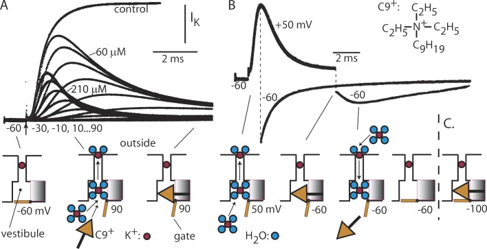
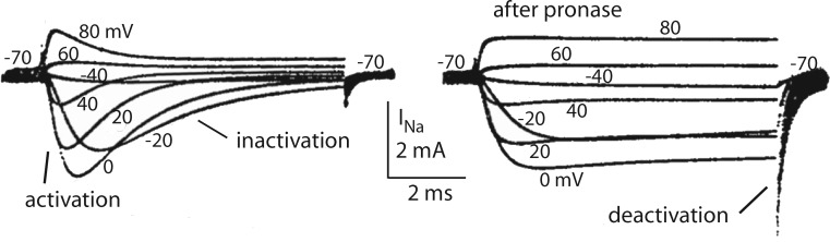
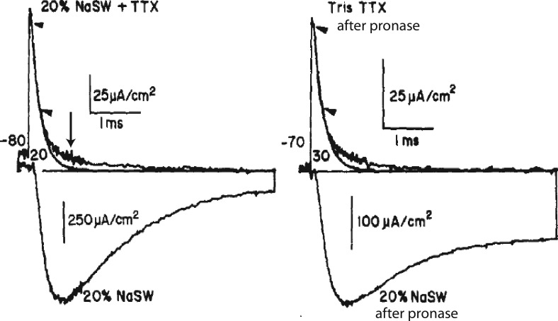
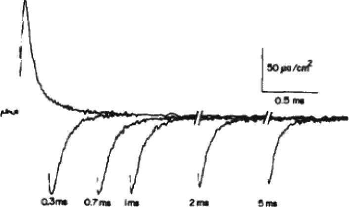
We are wired with conducting cables called axons that rapidly transmit electrical signals (e.g., "Ouch!") from, for example, the toe to the spinal cord. Because of the high internal resistance of axons (salt water rather than copper), a signal must be reinforced after traveling a short distance. Reinforcement is accomplished by ion channels, Na channels for detecting the signal and reinforcing it by driving it further positive (to near 50 mV) and K channels for then restoring it to the resting level (near -70 mV). The signal is called an action potential and has a duration of roughly a millisecond. The return of membrane voltage (Vm) to the resting level after an action potential is facilitated by "inactivation" of the Na channels: i.e., an internal particle diffuses into the mouth of any open Na channel and temporarily blocks it. Some types of K channels also show inactivation after being open for a time. N-type inactivation of K channels has a relatively fast time course and involves diffusion of the N-terminal of one of the channel's four identical subunits into the channel's inner mouth, if it is open. This mechanism is similar to Na channel inactivation. Both Na and K channels also display slower inactivation processes. C inactivation in K channels involves changes in the channel's outer mouth, the "selectivity filter," whose normal function is to prevent Na+ ions from entering the K channel. C inactivation deforms the filter so that neither K+ nor Na+ can pass.


Figures

Figure 1.
Figure 1.
C9+ block of IK resembles inactivation of INa. (A) IK (in squid axon) increases sigmoidally to a constant level after a depolarization to 90 mV (trace labeled control). With 60 µM C9+ inside the axon, IK increases normally and then “inactivates” (steps to −30 … 90 mV). C9+ enters more rapidly with 210 µM inside, resulting in smaller peak current and faster inactivation. The diagram shows the interpretation. At rest (−60 mV), a gate at the inner end of the channel protects a vestibule wide enough to hold a hydrated K+ ion, ∼8 Å in diameter. When the gate is opened by depolarization, K+ ions enter the vestibule, dehydrate as they pass through a narrow SF, and rehydrate at the outer end of the filter. C9+, also about ∼8 Å in diameter but with a nonyl tail, enters the vestibule much more slowly than K+, at a rate proportional to its concentration. Because its ethyl arms are covalently linked, it cannot shed them to enter the SF. Its hydrophobic nonyl chain binds to a hydrophobic region in the vestibule wall. Inactivation is faster at the higher C9+ concentration. (B) C9+ is forced out of the vestibule on repolarization to −60 mV by an influx of K+ ions. At the end of a short pulse, which results in a block of a few channels, IK is inward (external [K+] is high) and initially large, but decays rapidly as the channels deactivate. After a longer pulse, which inactivates most channels, IK is initially small, but increases as C9+ is driven from the vestibule by the in-moving K+. A channel liberated of C9+ can then close. (C) If Vm is returned to −100, the gate is slammed shut, trapping C9+ in the vestibule. In that case, the next depolarization, 2 s later, results in no IK: the channels are still C9+ blocked (not depicted). (Modified from Armstrong, 2007).
(Scheme 1)
(Scheme 1)
Figure 2.
Figure 2.
Pronase destroys inactivation when perfused internally through a squid axon. Families of superimposed INa traces are shown before and after pronase, in an axon with IK blocked by TEA. Before pronase INa increases after depolarization, as the channels activate, then decreases as inactivation occurs. On repolarization, there is a small inward tail of INa through the small fraction of channels that did not inactivate. After pronase inactivation does not occur, and upon repolarization, there is a large inward current through the still active channels. This current decays rapidly as the channels deactivate. Each trace in the figure was for a depolarization from −70 mV to the indicated voltage, with a 2-s interval between depolarizations. INa is outward at 60 and 80 mV, where the voltage drives Na+ outward through the channels. (Modified from Armstrong et al., 1973.)
Figure 3.
Figure 3.
Ig and INa. Ig is generated by the voltage-driven movement within the membrane of charged “particles,” now known to be arginine and lysine residues on the S4 helices. This movement forces the conformational changes that open and close the activation gate. In the traces shown, IK was eliminated by removing all K+ inside and out, and INa was reduced by lowering [Na+] (lower traces), or completely suppressed by adding tetrodotoxin. Capacitive current was removed by subtraction. (Left) For a step to 20 mV, Ig is outward and decays rapidly after its peak. The smooth trace is a fitted exponential to this fast phase of decay. A much smaller, slow component follows (arrow). It is too fast to be directly associated with inactivation of INa, but in Fig. 6 is related to a step preparatory to inactivation. (Right) After most of inactivation has been removed by pronase, the slow component is unchanged, further evidence that it is not directly related to inactivation.
Figure 4.
Figure 4.
Immobilization of gating charge by inactivation. Ig is shown for an axon with no Na+ or K+ either in or out, elicited by a step from –70 mV to 20 mV, with return to –70 mV after the interval indicated. The inward tail of Ig on repolarization decreases with time as the Na channels inactivate, immobilized by inactivation. Approximately 60% of total charge movement is immobilized by a long pulse.
Figure 5.
Figure 5.
Structural model of C inactivation: the outer SF and surroundings from the 2R9R structure of the Long et al. (2007) model. (A) Residues V377 and W362 stabilize Y373 in the outer carbonyl ring of the SF. Points of close contact (<4 Å) are indicated by black dots. V377 is from an adjacent subunit. (B) Proposed conformational wave coupling S4 movement to the SF, beginning when outward S4 motion brings R293 in contact with F344. Yellow bars indicate important hydrogen bonds. Breaking the bond between D375 and W362 destabilizes Y373, which rotates away from the pore axis, reducing the affinity of the outer filter site for K+. The mutation W362F(W434F in Shaker) also eliminates this hydrogen bond and permanently C-inactivates the channel (Perozo et al., 1993).
Figure 6.
Figure 6.
Ribbon diagrams. From a bacterial KcsA (green) and a Shaker-derived K channel (2R9R, red, purple). Structures were superimposed by aligning the SFs. The pore-lining TM2 segment of bacterial KcsA, which serves as a model for the closed channel, is almost straight. The outer half of the analogous pore-lining S6 segment of the 2R9R channel closely follows TM2 of KcsA near the outside and then bends away, part-way through the membrane, beginning near Gly marked on S6. Also shown for 2R9R are the S4 segment with positively charged residues in blue, the S4-5 linker (red), the S5 segment (purple, abbreviated), and two “hinges” (yellow). The curved arrows show guesses regarding the motions of S4, S4-5, and S6 as the channel closes. S4 moves downward, S4-5 pivots around a hinge at the junction of S4-5 with the S5 segment, and S4–S5 forces S6 to a position similar to the green KcsA helix,. Cross sections of the channels, taken at the arrow, are shown at the lower right. Superimposed on the cross sections is a circle representing a hydrated K+ ion, ∼8 Å in diameter. It is a good fit for the 2R9R channel, which is open. The KcsA channel has three hydrophobic seals (T107 is shown), which are too small for passage of a hydrated K+ ion. In good agreement with this experimental setup, the cross section shows that a single one of the four S6s (or TM2s) in closed position is sufficient to stop IK, which, at the gate, is a flux of hydrated K+.
Figure 7.
Figure 7.
The states of a sodium channel. Closed (I), activated (II), ready to inactivate (III), inactivated (IV), and closed-inactivated (V). The S4 segments of D2 and D4 are in black, S4-5 linkers in blue, and S6 gate region in brown. The QgTC of D2 is E2 F N2, and for D4, it is E4 F N4. (I) The closed state. The S4s are in the full-inward position, with both D2:R1 and D4:R1 at E of their respective QgTC, pinching closed the S6 gate sections. The SF is occupied by a Ca2+ ion, pulled in by negative internal Vm. The D3–D4 linker and its IFM motif are held away from the channel’s inner mouth by D4:S4. (II) D2:S4 and D4:S4 have moved outward, to the positions shown, allowing the S6 gates to open. The channel is conducting: a partially hydrated Na+ ion is in the SF, and a fully hydrated Na+ is in the gate region. Ap-A toxin is shown bound to the D4:S3-S4 linker, inhibiting further upward movement of D4:S4. (III) Ap-A toxin is either not present or has been displaced by prolonged depolarization. D4:S4 is fully activated, with K7 at E4. The inactivating particle is free to move upward (dashed arrow). (IV) The inactivating particle has moved into the inner mouth of the channel, stopping conduction. (V) On repolarization of the membrane, D2 (and D1, not depicted) have fully deactivated (R1 at E2) and closed the channel. R5 of D4 is at E4. Negative Vm has a) pulled a Ca2+ ion into the SF, and b) is forcing D4:S4 inward, which c) forces the inactivating particle out of the channel mouth, perhaps aided by the inward force on the Na+ ion, which is repelled by the Ca2+ ion in the SF. When the inactivating particle is dislodged, D4:S4 moves to fully deactivated position (R1 at E4), the S6 gate fully closes, and the channel has returned to condition I.

References

    1. Agnew W.S., Moore A.C., Levinson S.R., and Raftery M.A.. 1980. Identification of a large molecular weight peptide associated with a tetrodotoxin binding protein from the electroplax of Electrophorus electricus. Biochem. Biophys. Res. Commun. 92:860–866. 10.1016/0006-291X(80)90782-2 - DOI - PubMed
    1. Aldrich R.W., Corey D.P., and Stevens C.F.. 1983. A reinterpretation of mammalian sodium channel gating based on single channel recording. Nature. 306:436–441. 10.1038/306436a0 - DOI - PubMed
    1. Armstrong C.M. 1969. Inactivation of the potassium conductance and related phenomena caused by quaternary ammonium ion injection in squid axons. J. Gen. Physiol. 54:553–575. 10.1085/jgp.54.5.553 - DOI - PMC - PubMed
    1. Armstrong C.M. 1971. Interaction of tetraethylammonium ion derivatives with the potassium channels of giant axons. J. Gen. Physiol. 58:413–437. 10.1085/jgp.58.4.413 - DOI - PMC - PubMed
    1. Armstrong C.M. 1981. Sodium channels and gating currents. Physiol. Rev. 61:644–683. - PubMed