Review
. 2018 Feb 5;150(2):225-244.
doi: 10.1085/jgp.201711898. Epub 2017 Dec 12.

Structural insights into the mechanisms of CNBD channel function

Affiliations
Review

Structural insights into the mechanisms of CNBD channel function

Zachary M James et al. J Gen Physiol. .

Abstract

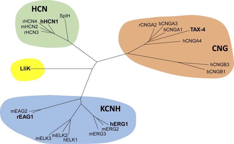
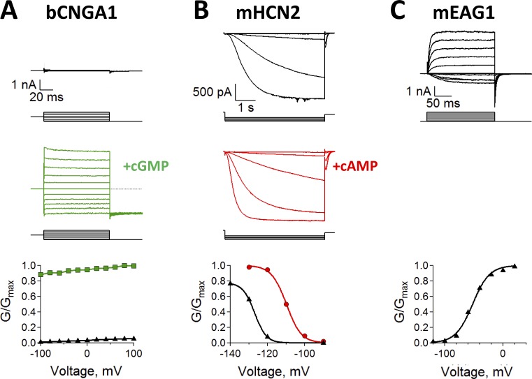
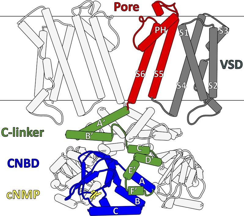
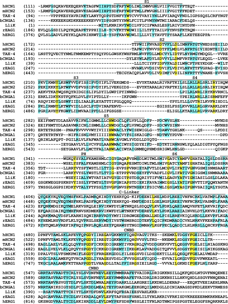
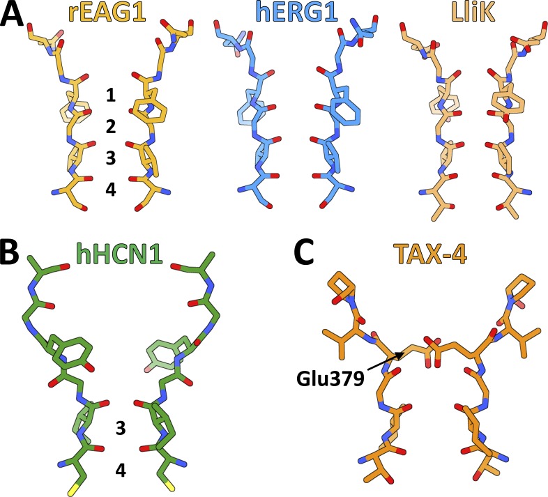
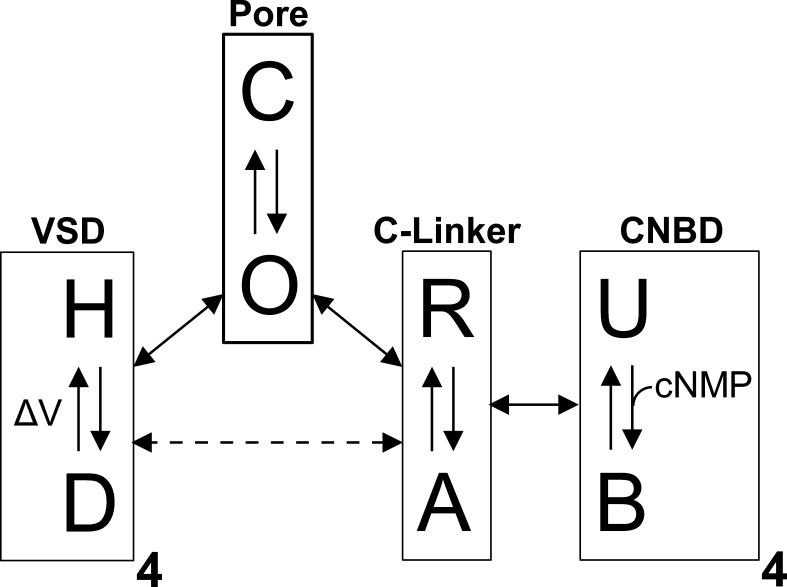
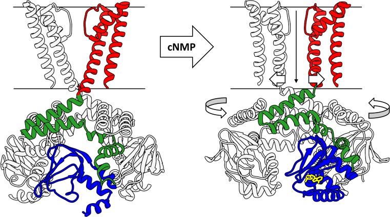
Cyclic nucleotide-binding domain (CNBD) channels are a family of ion channels in the voltage-gated K+ channel superfamily that play crucial roles in many physiological processes. CNBD channels are structurally similar but functionally very diverse. This family includes three subfamilies: (1) the cyclic nucleotide-gated (CNG) channels, which are cation-nonselective, voltage-independent, and cyclic nucleotide-gated; (2) the hyperpolarization-activated cyclic nucleotide-gated (HCN) channels, which are weakly K+ selective, hyperpolarization-activated, and cyclic nucleotide-gated; and (3) the ether-à-go-go-type (KCNH) channels, which are strongly K+ selective, depolarization-activated, and cyclic nucleotide-independent. Recently, several high-resolution structures have been reported for intact CNBD channels, providing a structural framework to better understand their diverse function. In this review, we compare and contrast the recent structures and discuss how they inform our understanding of ion selectivity, voltage-dependent gating, and cyclic nucleotide-dependent gating within this channel family.


Figures

Figure 1.
Figure 1.
Dendrogram of the CNBD cation channel family. This family contains three subfamilies: CNG channels, HCN channels, and KCNH channels. The five channels whose structures are discussed in this review (rEAG1, hERG1, hHCN1, TAX-4, and LliK) are highlighted in bold.
Figure 2.
Figure 2.
Diverse functional properties of CNBD channels. (A) Na+ currents recorded from bovine CNGA1 (bCNGA1) channels in the absence (top, black) and presence (middle, green) of saturating cGMP concentrations. Scale bar applies to both top and middle panels. Currents were measured by stepping from 0 mV to test potentials ranging from −100 mV to 100 mV, before stepping to a −100-mV tail potential. The conductance–voltage (G-V) relationship (bottom) was obtained from normalized tail currents. (B) K+ currents recorded from mouse HCN2 (mHCN2) channels in the absence (top, black) and presence (middle, red) of saturating cAMP concentrations. Scale bar applies to both top and middle panels. Currents were measured by stepping from 0 mV to test potentials ranging from −90 mV to −140 mV, before stepping to a 0-mV tail potential. The G-V curve (bottom) was obtained from normalized tail currents. (C) K+ Currents recorded from mouse EAG1 (mEAG1) channels in the absence of cyclic nucleotides (top, black). Currents were measured by stepping from −120 mV to test potentials ranging from −120 mV to 100 mV, before stepping to a −120-mV tail potential. The G-V curve (bottom) was obtained from normalized tail currents.
Figure 3.
Figure 3.
Core architecture of CNBD channels. For clarity, the diagram omits the transmembrane regions (VSDs, pore domains) of the front and back subunits, along with the CNBD of the back subunit. The core domains of one subunit are highlighted, and include a VSD (gray), a pore domain (red), a C-linker domain (green), and a CNBD (blue). A cyclic nucleotide (cNMP, yellow) is also shown within CNBD binding pocket. All figures depicting protein structure were generated using the UCSF Chimera software package (Pettersen et al., 2004).
Figure 4.
Figure 4.
Protein sequence alignment covering the core architecture of CNBD channels. Alignment includes the five channels discussed in this review (rEAG1, hERG1, hHCN1, TAX-4, and LliK), along with mouse HCN2 (mHCN2) and bovine CNGA1 (bCNGA1). Approximate boundaries of the transmembrane helices (S1–S6), pore helix (PH), and intracellular domains (C-linker, CNBD) are shown above the alignment. Cyan highlighting indicates strong sequence conservation, whereas yellow highlighting indicates complete conservation.
Figure 5.
Figure 5.
Overview of the five CNBD channel structures. For each channel, the core domains of one subunit are colored as in Fig. 3 (VSD in gray, pore domain in red, C-linker domain in green, and CNBD in blue). Additional domains and/or associated regulatory proteins are colored separately, whereas bound cyclic nucleotides or intrinsic ligand residues are shown as yellow sticks. (A) The rEAG1 (PDB ID: 5K7L) channel, with the N-terminal eag domain shown in orange and one bound Ca2+-calmodulin shown in cyan. (B) The hERG1 (PDB ID: 5VA1) channel, with the N-terminal eag domain shown in orange. (C) The hHCN1 channel bound by cAMP (PDB ID: 5U6P), with the N-terminal HCN domain shown in light brown. (D) C. elegans CNG channel (TAX-4, PDB ID: 5H3O) bound by cGMP. (E) Leptospira licerasiae bacterial CNG channel (LliK, PDB ID: 5V4S) in the presence of cAMP.
Figure 6.
Figure 6.
Selectivity filters of CNBD channels. (A) Stick representations of selectivity filters from the highly K+-selective rEAG1, hERG1, and LliK channels. Cation-binding sites 1–4, composed of backbone carbonyl groups and Ser(Thr) side chains, are labeled in the rEAG1 selectivity filter. (B) Stick representation of the weakly selective hHCN1 selectivity filter, with retained cation binding sites 3 and 4 labeled. (C) Stick representation of the nonselective TAX-4 selectivity filter, with highly conserved residue Glu379 labeled.
Figure 7.
Figure 7.
Modular gating scheme for ion channel function. CNBD channels may be treated as a collection of energetically coupled modules, each capable of independently transitioning between different states. The VSDs can adopt hyperpolarized (H) or depolarized (D) states; the CNBDs can adopt unbound (U) or bound (B) states; the C-linker can adopt a resting (R) or active (A) state; and the pore can adopt a closed (C) or open (O) state. The conformation adopted by a given module influences the favorability of connected modules occupying a particular state. Energetic coupling between modules is indicated by the double-headed arrows, and equilibration of a module between different conformational states is indicated by the single-headed arrows.
Figure 8.
Figure 8.
Comparison of pore domains in CNBD channels. (A) Structural alignment of rEAG1 and hERG1 pore domains, with intracellular gating residues (Gln476 in rEAG1; Gln664 in hERG1) labeled and shown as sticks. VSDs from one subunit are also shown. Arrows highlight the relative displacement of the hERG1 S5 and S6 helices toward the VSD to permit dilation of the intracellular gate. (B) Structural alignment of the rEAG1 and hHCN1 pore domains, with gating residues (Gln476 in rEAG1; Val390, Thr394, and Gln398 in hHCN1) shown as sticks and overlapping gating residues (Gln476 in rEAG1; Gln398 in hHCN1) highlighted by a dashed circle. (C) Structural alignment of the hHCN1 and LliK pore domains, with gating residues (Tyr224 and Ile228 in LliK; Val390, Thr394, and Gln398 in hHCN1) shown as sticks, and overlapping gating residues (Val390 in hHCN1, Ile228 in LliK) highlighted by a dashed circle. (D) Structural alignment of hERG1 and TAX-4 pore domains, with the hERG1 gating residue Gln664 shown as sticks.
Figure 9.
Figure 9.
Voltage-sensor domains of CNBD channels. In top panels, the C-terminal portion of S3 is omitted for clarity, and S2 residues (Phe, Asp) contributing to the charge-transfer center and basic residues along S4 (Arg, Lys) are shown as sticks. In bottom panels, the VSDs are rotated by 45° relative to the top panels, with the S4 helices individually colored. (A) Structurally aligned VSDs of rEAG1 and hERG1, with rEAG1 charge-transfer center residues Phe261 and Asp264, along with residue Arg336 (R4) occupying the charge-transfer center, labeled in the top panel. (B) VSD of hHCN1, with residue Arg273 (R5) occupying the charge-transfer center labeled in the top panel. (C) VSD of TAX-4, with the three regions of S4 (S4a, S4b, and S4c) labeled in the bottom panel. (D) VSD of LliK.
Figure 10.
Figure 10.
Comparison of intracellular domains. (A) Structural alignment of unliganded (PDB ID: 5U6O) and cAMP-bound hHCN1 CNBDs, with cAMP shown in yellow sticks. Arrows highlight the rotation of the C-helix toward the β-roll after cyclic nucleotide binding, along with upward movement of the C-linker E′- and F′-helices. (B) Structural alignment of the cAMP-bound CNBDs from hHCN1 and mouse HCN2 (PDB ID: 1Q5O), which adopt essentially identical conformations. Bound cAMP shown in yellow sticks. (C) Structural alignment of the cAMP-bound hHCN1 CNBD and the rEAG1 CNBHD. Bound cAMP is shown in yellow sticks, and the rEAG1 intrinsic ligand residues (Tyr672-Asn673-Leu674) are shown as sticks colored like the rEAG1 ribbon structure. (D) Structural alignment of the rEAG1 eag domain (orange) + CNBHD (blue, from an adjacent subunit) with the cocrystal structure of the mEAG1 eag domain + CNBHD (gray, PDB ID: 4LLO). Intrinsic ligand residues (yellow for rEAG1, gray for mEAG1) are shown as sticks.
Figure 11.
Figure 11.
Rotation of the C-terminal domains associated with CNBD channel gating. (A) Top-down view of the unliganded and cAMP-bound hHCN1 structures aligned by their pore domains, with the view clipped to highlight the C-linker domains. Alignment reveals a subtle counterclockwise rotation of the C-linker/CNBD in cAMP-bound hHCN1, relative to the apo structure. (B) Top-down view of the rEAG1 (closed gate) and hERG1 (open gate) structures aligned by their pore domains, with the view clipped as in A. Alignment reveals a dramatic counterclockwise rotation of the hERG1 C-linker/CNBHD relative to rEAG1.
Figure 12.
Figure 12.
Proposed mechanism for cyclic nucleotide–dependent activation of CNBD channels. In the absence of cyclic nucleotides (left), the C-linker/CNBD adopts a resting state that exerts a tonic inhibitory force on the pore domain, maintaining it in the closed state. Cyclic nucleotide binding to the CNBDs promotes the transition of the C-linker to its active state, relieving this inhibition. The dis-inhibited pore domain can now dilate at the intracellular gate, inducing a counterclockwise rotation of the C-terminal domains.

Similar articles

Cited by

References

    1. Akimoto M., Zhang Z., Boulton S., Selvaratnam R., VanSchouwen B., Gloyd M., Accili E.A., Lange O.F., and Melacini G.. 2014. A mechanism for the auto-inhibition of hyperpolarization-activated cyclic nucleotide-gated (HCN) channel opening and its relief by cAMP. J. Biol. Chem. 289:22205–22220. 10.1074/jbc.M114.572164 - DOI - PMC - PubMed
    1. Altomare C., Terragni B., Brioschi C., Milanesi R., Pagliuca C., Viscomi C., Moroni A., Baruscotti M., and DiFrancesco D.. 2003. Heteromeric HCN1-HCN4 channels: a comparison with native pacemaker channels from the rabbit sinoatrial node. J. Physiol. 549:347–359. 10.1113/jphysiol.2002.027698 - DOI - PMC - PubMed
    1. Anderson J.A., Huprikar S.S., Kochian L.V., Lucas W.J., and Gaber R.F.. 1992. Functional expression of a probable Arabidopsis thaliana potassium channel in Saccharomyces cerevisiae. Proc. Natl. Acad. Sci. USA. 89:3736–3740. 10.1073/pnas.89.9.3736 - DOI - PMC - PubMed
    1. Bankston J.R., Camp S.S., DiMaio F., Lewis A.S., Chetkovich D.M., and Zagotta W.N.. 2012. Structure and stoichiometry of an accessory subunit TRIP8b interaction with hyperpolarization-activated cyclic nucleotide-gated channels. Proc. Natl. Acad. Sci. USA. 109:7899–7904. 10.1073/pnas.1201997109 - DOI - PMC - PubMed
    1. Benarroch E.E. 2013. HCN channels: Function and clinical implications. Neurology. 80:304–310. 10.1212/WNL.0b013e31827dec42 - DOI - PubMed

Publication types

MeSH terms

Substances

LinkOut - more resources