. 2017 Dec 13;552(7684):214-218.
doi: 10.1038/nature24670.

An electric-eel-inspired soft power source from stacked hydrogels

Affiliations

An electric-eel-inspired soft power source from stacked hydrogels

Thomas B H Schroeder et al. Nature. .

Abstract

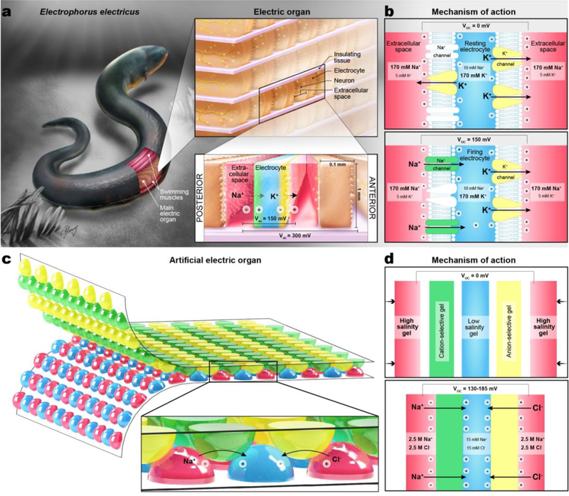
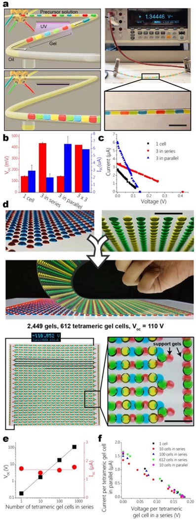
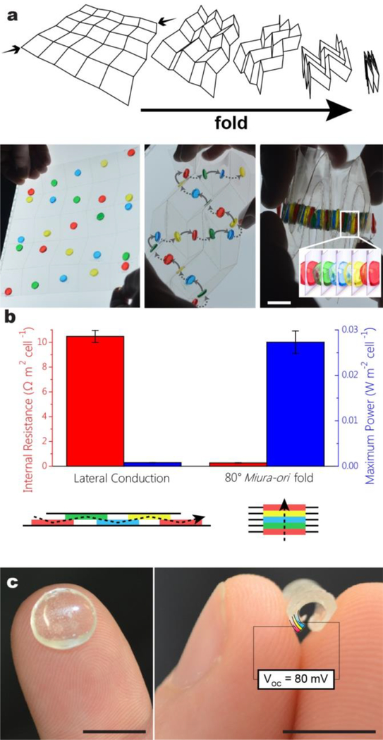
Progress towards the integration of technology into living organisms requires electrical power sources that are biocompatible, mechanically flexible, and able to harness the chemical energy available inside biological systems. Conventional batteries were not designed with these criteria in mind. The electric organ of the knifefish Electrophorus electricus (commonly known as the electric eel) is, however, an example of an electrical power source that operates within biological constraints while featuring power characteristics that include peak potential differences of 600 volts and currents of 1 ampere. Here we introduce an electric-eel-inspired power concept that uses gradients of ions between miniature polyacrylamide hydrogel compartments bounded by a repeating sequence of cation- and anion-selective hydrogel membranes. The system uses a scalable stacking or folding geometry that generates 110 volts at open circuit or 27 milliwatts per square metre per gel cell upon simultaneous, self-registered mechanical contact activation of thousands of gel compartments in series while circumventing power dissipation before contact. Unlike typical batteries, these systems are soft, flexible, transparent, and potentially biocompatible. These characteristics suggest that artificial electric organs could be used to power next-generation implant materials such as pacemakers, implantable sensors, or prosthetic devices in hybrids of living and non-living systems.


Conflict of interest statement

Author Information:

The authors declare no competing financial interests.

Figures

Figure 1.
Figure 1.
Charged monomers used in charge-selective “membrane” gels. a, 3-sulfopropyl acrylate, a component of the cation-selective gel. b, (3-acrylamidopropyl)trimethylammonium, a component of the anion-selective gel.
Figure 2 |
Figure 2 |
Self-discharge of artificial electric organ over time after contact between all gels with and without exposure to ambient air. Curves were fit with a single exponential decay function (dotted curves); the half-time for each was 40 min. The artificial electric organ was assembled as described in Supplementary Information section S3. Video 1 shows a fluidic implementation of the artificial electric organ which puts gels into contact sequentially rather than simultaneously. Large-scale implementations of similar sequential positioning schemes would be prone to power loss from gradient depletion.
Figure 3 |
Figure 3 |
The artificial electric organ can be recharged. Experimental details in Supplementary Information section S3. a, Current versus time traces of ten discharges of a single tetrameric gel cell at short circuit following recharging. Initial discharge shown in black; subsequent discharges in the following order: red, blue, magenta, green, navy, purple, plum, wine, olive. b, Bar graph of normalized integrals of discharge curves.
Figure 4 |
Figure 4 |
The printed 45° Miura-ori gel cell geometry. Dotted lines of a single color indicate gels forming a series. Different colors indicate parallel sequences. This fold geometry is scalable both in series for higher voltage output and in parallel for higher current.
Figure 5 |
Figure 5 |
Internal resistance (black squares) and power density (red circles) of gel cells as a function of thickness of low-salinity gel. The thicknesses of all other gels were held constant at 1 mm.
Figure 6 |
Figure 6 |
Equivalent circuit of an artificial electric organ connected to a load resistance. The elements within the dotted line represent the contribution of a single gel cell; these can be added in series or in parallel. The impedance of the voltmeter used exceeded 10 GΩ; current through this pathway was assumed to be negligible.
Figure 1 |
Figure 1 |. Morphology and mechanism of action of the eel’s electric organ and the artificial electric organ.
a, Arrangement of electrocytes within the electric organs of Electrophorus electricus. Close-up shows ion fluxes in the firing state. b, Mechanism of voltage generation in electrocytes. Each cell’s posterior membrane is innervated and densely packed with voltage-gated Na+ channels; the anterior membrane is non-innervated and has papillar projections extending into the extracellular compartment that increase its surface area. In the resting state, open K+ channels in both membranes produce equal and opposite transmembrane potentials of −85 mV, so the total transcellular potential is zero. During an impulse, the Na+ channels in the posterior membrane open and K+ channels close in response to neural signals, generating an action potential of +65 mV from the resulting change in relative permeability to Na+ and K+ ions (see Section S1) and a total transcellular potential across both membranes of +150 mV. c, Artificial electric organ in its printed implementation. In this and all subsequent figures, red hydrogel contains concentrated NaCl and was polymerized from neutral monomers, green gel was polymerized from negatively-charged monomers and is cation-selective, blue gel contains dilute NaCl and was polymerized from neutral monomers, and yellow gel was polymerized from positively-charged monomers and is anion-selective. d, Mechanism of voltage generation in artificial electric organ. Mechanical contact brings together a sequence of gels such that ionic gradients are formed across alternating charge-selective membranes, producing potentials across each membrane that add up as tetramers and can be stacked in series of thousands of gels (see Section S1).
Figure 2 |
Figure 2 |. Fluidic and printed artificial electric organs.
a, Left: Cartoon of a fluidic artificial electric organ before and after contact activation. Aqueous plugs of hydrogel precursor solution were generated in mineral oil, cured with a UV lamp, and sequentially brought into mechanical contact after passing a small aperture in the tubing that allowed the interstitial oil to escape. Right: Photograph of a fluidic artificial electric organ with 10 tetrameric gel cells generating 1.34 V. Scale bar = 1 cm. b, Open-circuit voltage and short-circuit current characteristics of fluidic artificial electric organ. Open-circuit voltages (red bars) scale linearly when tetrameric gel cells are added in series; short-circuit currents (blue bars) scale linearly when tetrameric gel cells are added in parallel. (Error bars show s.d., N = 3 except for 3×3, where N = 1). c, Plot of current and voltage in response to various external loads for one tetrameric gel cell (black squares), three cells in series (red circles), and three cells in parallel (blue triangles). d, Photographs of large complementary arrays of printed hydrogel lenses combining to form continuous series of 2,449 gels with serpentine geometry. Support gels are used for mechanical stability and do not contribute to the system electrically. Scale bar = 1 cm. e, Open circuit voltage and short circuit current characteristics of printed artificial electric organs as a function of the number of tetrameric gel cells in a series. f. Normalized current-voltage relations of various numbers of tetrameric cells added in series and in parallel. The voltage axis is normalized by the number of cells in a series; the current axis is normalized by the number of series that are arranged in parallel. All points fall on one curve, as expected for a scalable system.
Figure 3 |
Figure 3 |. Artificial electric organ morphologies based on thin hydrogel films.
a, Schematic and photographs of Miura-ori folding. A single motion compresses a two-dimensional array of panels into a self-registered folded state where all panels overlap, generating a one-dimensional sequence. This morphology was used to generate flat and large contact areas between a series of thin gel films, which conducted ions from gel to gel through holes in the supporting polyester substrate. Scale bar = 1 cm. b, Area-normalized internal resistance (red) and maximum power (blue) per tetrameric gel cell with 0.7 mm thick gel films arranged either laterally in a manner that approximates the relative geometry of the serpentine implementation or in a Miura-ori-assembled stack (Error bars show s.e.m., N = 3) Section S4). The stack geometry imparts a 40-fold reduction in resistance and a corresponding 40-fold improvement in maximum power output. c, Flexible and transparent artificial electric organ prototype with the shape of a contact lens composed of a gel trilayer of high salinity gel (indicated by a false-colored section in red), anion-selective gel (yellow), and low salinity gel (blue) with a total thickness of 1.2 mm that produced an open-circuit voltage of 80 mV. Scale bars = 1 cm.

Comment in

Similar articles

Cited by

References

    1. Bennett MVL Electric Organs in Fish Physiology (ed. Randall WSH. and D. J.) 5, 347–491 (Academic Press, 1971).
    1. Gotter AL, Kaetzel MA & Dedman JR Electrophorus electricus as a model system for the study of membrane excitability. Comp. Biochem. Physiol. A. Mol. Integr. Physiol 119, 225–241 (1998). - PubMed
    1. Xu J, Sigworth FJ & LaVan DA Synthetic Protocells to Mimic and Test Cell Function. Adv. Mater. 22, 120–127 (2010). - PMC - PubMed
    1. Sun H, Fu X, Xie S, Jiang Y & Peng H Electrochemical Capacitors with High Output Voltages that Mimic Electric Eels. Adv. Mater. 28, 2070–2076 (2016). - PubMed
    1. Kim D-H et al. Epidermal Electronics. Science 333, 838–843 (2011). - PubMed

Extended Data References:

    1. Schoffeniels E Ion Movements Studied with Single Isolated Electroplax. Ann. N. Y. Acad. Sci. 81, 285–306 (1959). - PubMed
    1. Altamirano M & Coates CW Effect of potassium on electroplax of electrophorus electricus. J. Cell. Comp. Physiol. 49, 69–101 (1957). - PubMed
    1. Nakamura Y, Nakajima S & Grundfest H Analysis of spike electrogenesis and depolarizing K inactivation in electroplaques of Electrophorus electricus, L. J. Gen. Physiol. 49, 321–349 (1965). - PMC - PubMed

Publication types