. 2017 Mar:9:1-11.
doi: 10.1016/j.biotri.2016.11.002. Epub 2016 Nov 30.

ESTABLISHING A LIVE CARTILAGE-ON-CARTILAGE INTERFACE FOR TRIBOLOGICAL TESTING

Affiliations

ESTABLISHING A LIVE CARTILAGE-ON-CARTILAGE INTERFACE FOR TRIBOLOGICAL TESTING

Robert L Trevino et al. Biotribology (Oxf). 2017 Mar.

Abstract

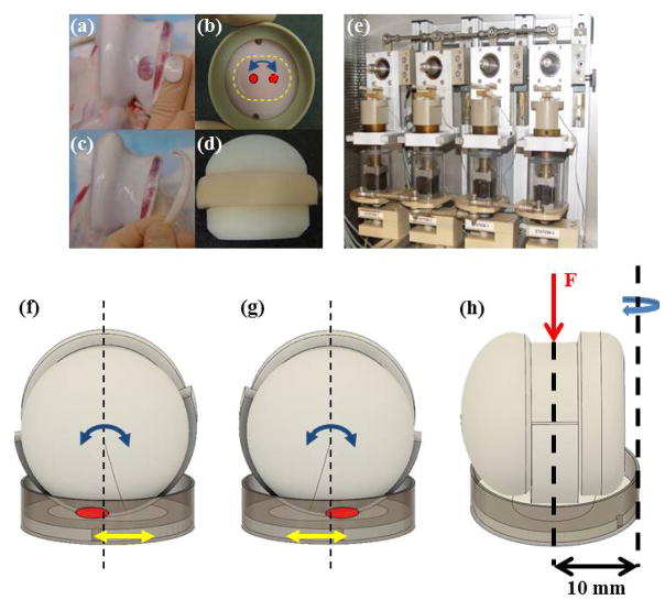
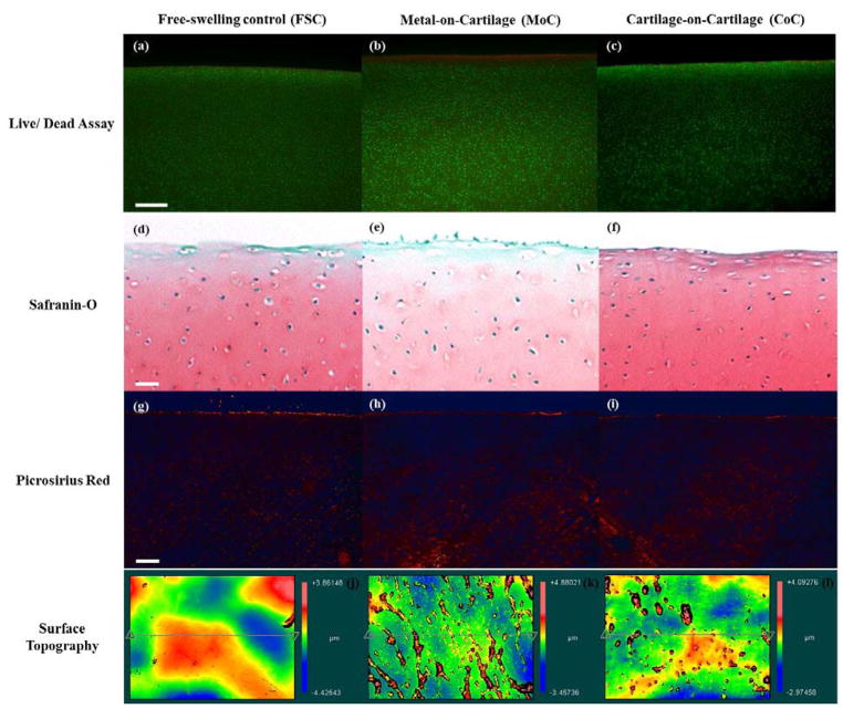
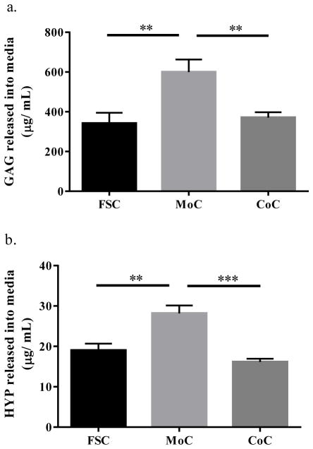
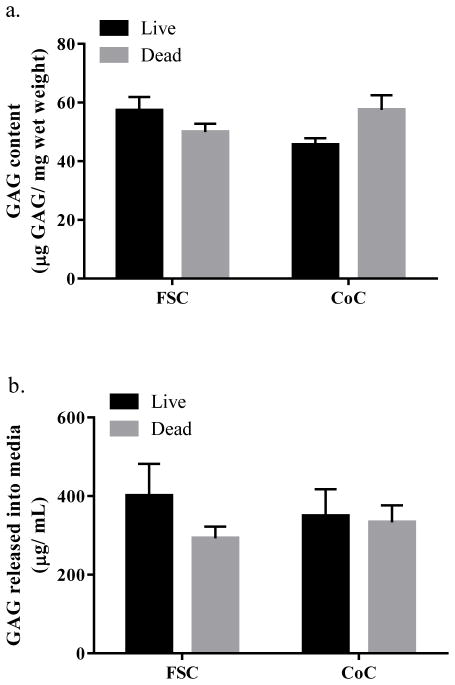
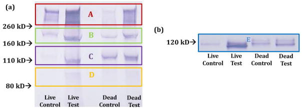
Mechano-biochemical wear encompasses the tribological interplay between biological and mechanical mechanisms responsible for cartilage wear and degradation. The aim of this study was to develop and start validating a novel tribological testing system, which better resembles the natural joint environment through incorporating a live cartilage-on-cartilage articulating interface, joint specific kinematics, and the application of controlled mechanical stimuli for the measurement of biological responses in order to study the mechano-biochemical wear of cartilage. The study entailed two parts. In Part 1, the novel testing rig was used to compare two bearing systems: (a) cartilage articulating against cartilage (CoC) and (b) metal articulating against cartilage (MoC). The clinically relevant MoC, which is also a common tribological interface for evaluating cartilage wear, should produce more wear to agree with clinical observations. In Part II, the novel testing system was used to determine how wear is affected by tissue viability in live and dead CoC articulations. For both parts, bovine cartilage explants were harvested and tribologically tested for three consecutive days. Wear was defined as release of glycosaminoglycans into the media and as evaluation of the tissue structure. For Part I, we found that the live CoC articulation did not cause damage to the cartilage, to the extent of being comparable to the free swelling controls, whereas the MoC articulation caused decreased cell viability, extracellular matrix disruption, and increased wear when compared to CoC, and consistent with clinical data. These results provided confidence that this novel testing system will be adequate to screen new biomaterials for articulation against cartilage, such as in hemiarthroplasty. For Part II, the live and dead cartilage articulation yielded similar wear as determined by the release of proteoglycans and aggrecan fragments, suggesting that keeping the cartilage alive may not be essential for short term wear tests. However, the biosynthesis of glycosaminoglycans was significantly higher due to live CoC articulation than due to the corresponding live free swelling controls, indicating that articulation stimulated cell activity. Moving forward, the cell response to mechanical stimuli and the underlying mechano-biochemical wear mechanisms need to be further studied for a complete picture of tissue degradation.

Keywords: cartilage; cartilage mechanics; joint motion simulation; tribology- wear.


Conflict of interest statement

Conflicts of Interest: None

Figures

Figure 1
Figure 1
Image of the disc removed from trochlear groove (a) and secured in semi-confined compression in the polyethylene wafer in a PEEK cup (b). Image of the cartilage strip removed from the trochlear rim (c) and then secured to the polyethylene ball adapted (d). (e) Image of the tribological testing device housed in an incubator where the ball set at the top of the station and rotated at a frequency of 0.5 Hz and a stroke of 30° while the explant rotated at 0.1 Hz and a stroke of 15°. This motion with a contact area of roughly 20 mm2 creates a 5.2 mm curvilinear wear path. (f–g) Diagram of the migrating contact point (red circle) on the cartilage disc surface through dual-axial rotation of the disc/cup (yellow arrow) and of the strip/ball (blue arrow), which can also be seen from contact points marked in Figure 1b. (h) The curvilinear translation shown in Figures 1b, 1f, and 1g was technically realized through offsetting the rotational axis of the disc from the loading axis by 10 mm.
Figure 2
Figure 2
Schema of the aggrecan core protein (with GAG chains removed)[–52]. AHP0022 detects bands A–D and anti-AGEG detects band E. Arrows delineate definite ADAMTS cleavage sites for bands A, B, D, and E[51] while bands A–E are all detectable aggrecan fragments. G1, G2, G3 represent the globular domains.
Figure 3
Figure 3
Live/dead cross-sections of the cartilage explants from (a) FSC, (b) MoC, and (c) CoC groups stained with calcein AM (green; living chondrocytes) and ethidium homodimer (red; dead chondrocytes) at 5x. Representative cross-sections of the cartilage explants from (d) FSC, (e) MoC, and (f) CoC groups stained with Safranin-O for GAG at 4x magnification. Representative cross-sections of the cartilage explants from (g) FSC, (h) MoC, and (i) CoC groups stained with Picrosirius red for collagen at 4x magnification. Representative topographical plots of average SRz values for (j) FSC, (k) MoC, and (l) CoC. (g) represents the native microfeatures of cartilage, while (h) displays an increase in microfibrillation features as compared to (g)and (i). Bar represents 250 μm.
Figure 4
Figure 4
(a) GAG released into the media. (b) HYP released into the media. CoC samples are corrected to account for two interacting cartilage surfaces which both release matrix contents into the media. Data represents means +/− SEM for n=10–12 explants. **: p<0.01, ***: p<0.001 as compared to MoC.
Figure 5
Figure 5
Radiolabeled 35SO4-incorporation for live CoC articulated explants and strips, normalized to live FSC. Dotted line represents FSC. Data represents means +/− SEM for n=8 explants and strips. *: p<0.05, **: p<0.01 as compared to FSC.
Figure 6
Figure 6
(a) GAG content of cartilage plugs. (b) GAG released into media. Data represents means +/− SEM for n=6 (GAG content) and n=12 (GAG release).
Figure 7
Figure 7
Western blot results from the use of the antibody AHP0022 (a) and anti-AGEG (b). AHP0022 resulted in multiple bands as the antibody is to the interglobular domains in G1 and G2. Anti-AGEG resulted in a single band representing a specific aggrecan fragment. At least two samples were run per condition to confirm Western blot results. Figure 2 serves as the band reference.

References

    1. Zhang L, Hu J, Athanasiou KA. The Role of Tissue Engineering in Articular Cartilage Repair and Regeneration. Crit Rev Biomed Eng. 2009;37:1–57. - PMC - PubMed
    1. Katta J, Jin Z, Ingham E, Fisher J. Biotribology of articular cartilage—A review of the recent advances. Med Eng Phys. 2008;30:1349–1363. doi: 10.1016/j.medengphy.2008.09.004. - DOI - PubMed
    1. Rabinowicz E. Friction and Wear of Materials. 2. Wiley-Interscience; New York, NY: 1995.
    1. Waldman SD, Couto DC, Grynpas MD, Pilliar RM, Kandel RA. Multi-axial mechanical stimulation of tissue engineered cartilage: review. Eur Cell Mater. 2007;13:66–73. discussion 73–74. - PubMed
    1. Mankin H, Mow VC, Buckwalter JA, Iannotti J, Ratcliffe A. Orthop Basic Sci. Chapter 1. American Academy of Orthopaedic Surgeons; Columbus, OH: 1994. Form and function of articular cartilage; pp. 1–44.

LinkOut - more resources