Review
. 2018 Apr;115(4):815-830.
doi: 10.1002/bit.26519. Epub 2018 Feb 21.

Microfluidic platforms for the study of neuronal injury in vitro

Affiliations
Review

Microfluidic platforms for the study of neuronal injury in vitro

Anil B Shrirao et al. Biotechnol Bioeng. 2018 Apr.

Abstract

Traumatic brain injury (TBI) affects 5.3 million people in the United States, and there are 12,500 new cases of spinal cord injury (SCI) every year. There is yet a significant need for in vitro models of TBI and SCI in order to understand the biological mechanisms underlying central nervous system (CNS) injury and to identify and test therapeutics to aid in recovery from neuronal injuries. While TBI or SCI studies have been aided with traditional in vivo and in vitro models, the innate limitations in specificity of injury, isolation of neuronal regions, and reproducibility of these models can decrease their usefulness in examining the neurobiology of injury. Microfluidic devices provide several advantages over traditional methods by allowing researchers to (1) examine the effect of injury on specific neural components, (2) fluidically isolate neuronal regions to examine specific effects on subcellular components, and (3) reproducibly create a variety of injuries to model TBI and SCI. These microfluidic devices are adaptable for modeling a wide range of injuries, and in this review, we will examine different methodologies and models recently utilized to examine neuronal injury. Specifically, we will examine vacuum-assisted axotomy, physical injury, chemical injury, and laser-based axotomy. Finally, we will discuss the benefits and downsides to each type of injury model and discuss how researchers can use these parameters to pick a particular microfluidic device to model CNS injury.

Keywords: axotomy; chemical and physical neuronal injury; microfluidic neuronal culture; spinal cord injury; traumatic brain injury; vacuum-assisted and laser-based neuronal injury.


Conflict of interest statement

Conflicts of interest

There are no conflicts of interest to declare.

Figures

Figure 1
Figure 1
Microfluidic Neuronal culture devices. (A) Original Campenot chamber design. Neurites grow through scratches into adjacent chambers (Campenot 1977). (B) Improvement to Campenot device using microfluidics (Taylor et al. 2005). Precise microfluidic channels allow for consistent and reproducible neurite isolation and fluidic isolation of the separate chambers.
Figure 2
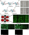
Figure 2
Microfluidic device for axonal injury by vacuum aspiration. (A) Left: Typical protocol for vacuum-assisted axotomy (Kim et al. 2012). Top Right: Phase contrast images of neurons grown in microfluidic device before and after application of vacuum-assisted axotomy. Neuronal soma are visibly undisturbed after injury (Park et al. 2006). (B) Modified device to apply vacuum injury with neurons expressing GFP after appropriate lentiviral infection with cell bodies in the center and axonal growth guided through microgrooves in side compartments. (C) Vacuum aspiration injury in the right chamber triggered retrograde signals that induced robust c-Jun phosphorylation. Microfluidic cultures were immunostained to detect phospho-cJun (pcJun) and Neurofilament. The retrograde signaling is tracked from uninjured and injured axon chambers on either side to the central cell body chamber(Holland et al. 2016).
Figure 3
Figure 3
Uniaxial Strain Microfluidic Platform for Organotypic Slice Culture. (A) Platform schematic depicting PDMS deflection after the application of pressure into pneumatic valve. (B) Top view of microfluidic device. (C) Time progression of delayed elastic effect on a single axon after application of 42% strain, i) before injury, ii) after injury t=0 min, iii) 20 mins, iv) 50 mins, v) 75 mins, vi) 210 mins, vii) 24hrs. Arrows show individual “waves/undulations” and arrow heads show beading(Dolle et al. 2013).
Figure 4
Figure 4
Microfluidic device to perform injury using compression pad. Microfluidic device controls for neuronal growth through microchannels into injury region. Application of pressure causes a downward deflection of the injury pad and compression injury of axon growing underneath. (B) Wallerian degeneration (nodal swellings) observed when a tau-labeled (microtubule marker) axon was subjected to severe (235 kPa) compression injury. After injury, the transected axon tip (white arrows) first retracted (30 mins), and then began to reform a growth cone (1 h 30 mins). Dotted lines demarcate the injury pad region. Scale bar 25 mm (Hosmane et al. 2011).
Figure 5
Figure 5
Microfluidic platforms to performchemical injury. (A) Schematic of five chamber microfluidic device. Fluidic isolation between chambers allows for investigation of effects of neural networks after application of chemical injury to one of the chambers (Samson et al. 2016). (B) Schematic of highly complex three layer compartmentalized microfluidic platform. (C) Isolation of cell body and axonal growth. (D) Axonal chamber with inlet for introducing treatments and outlet for media changes. (E) Differential fluid levels ensure fluidic isolation between somal and axonal chamber during treatment or media changes. (F) Axonal degeneration induced by injecting CSPG treatment in axonal chamber. Cells were stained with Calcein-AM(Kim et al. 2016).
Figure 6
Figure 6
Integrated microfluidic system developed to examine the effects of glial co-culture and pharmacological intervention on axonal degeneration and regeneration after chemical injury. (A) Image of dye-loaded device. B. Schematic displaying microvalve mechanism. (C) Various modes of intervention performed utilizing the integrated microfluidic system (Li et al. 2012).
Figure 7
Figure 7
Microfluidic devices to perform laser assisted neuronal injury. (A) Microfluidic device to perform laser-based axotomy. (B) Schematic showing axotomy of single axons grown through microfluidic channels with an integrated laser. (C) Microfluidic device for axotomy of single axons in vivo (Samara et al. 2010). (D) Drosophila or C. elegans are held in place with microfluidic channels, and single axons are visualized and axotomized via integrated optical components (Ghannad-Rezaie et al. 2012). (E-F) Axonal regeneration after (E) a partial defect created using single 400 nJ pulse and (F) a complete transection created using single 800 nJ pulse in a 25 μm-wide axon bundle. Arrows pointing initial dieback and growth cones (Hellman et al. 2010).

References

    1. Ben-Yakar A, Bourgeois F. Ultrafast laser nanosurgery in microfluidics for genome-wide screenings. Current opinion in biotechnology. 2009;20(1):100–105. - PMC - PubMed
    1. Benam KH, Dauth S, Hassell B, Herland A, Jain A, Jang K-J, Karalis K, Kim HJ, MacQueen L, Mahmoodian R. Engineered in vitro disease models. Annual Review of Pathology: Mechanisms of Disease. 2015;10:195–262. - PubMed
    1. Brunden KR, Ballatore C, Lee VM, Smith AB, 3rd, Trojanowski JQ. Brain-penetrant microtubule-stabilizing compounds as potential therapeutic agents for tauopathies. Biochem Soc Trans. 2012;40(4):661–6. - PMC - PubMed
    1. Campenot RB. Local control of neurite development by nerve growth factor. Proceedings of the National Academy of Sciences. 1977;74(10):4516–4519. - PMC - PubMed
    1. Center NSCIS. Facts and Figures at a Glance. Birmingham, AL: University of Alabama at Birmingham; 2015. pp. 1–2.

Publication types