Review
. 2017 Oct;7(5):507-526.
doi: 10.21037/cdt.2017.01.12.

3D printing from cardiovascular CT: a practical guide and review

Affiliations
Review

3D printing from cardiovascular CT: a practical guide and review

James M Otton et al. Cardiovasc Diagn Ther. 2017 Oct.

Abstract

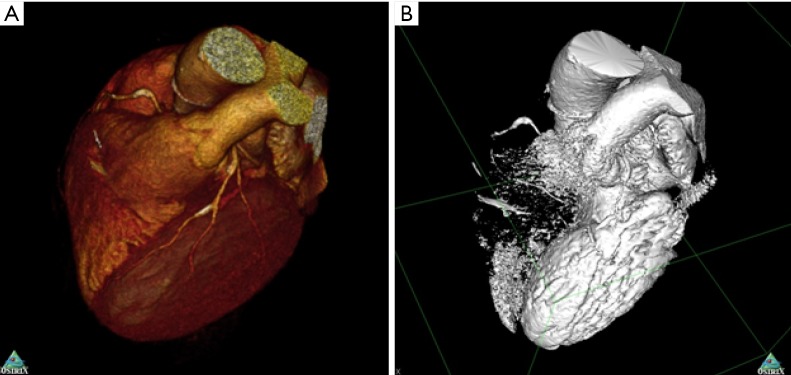
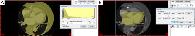
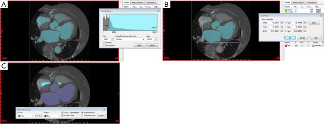
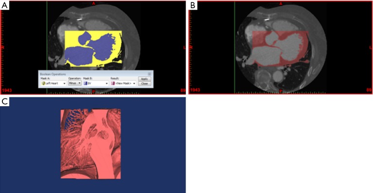
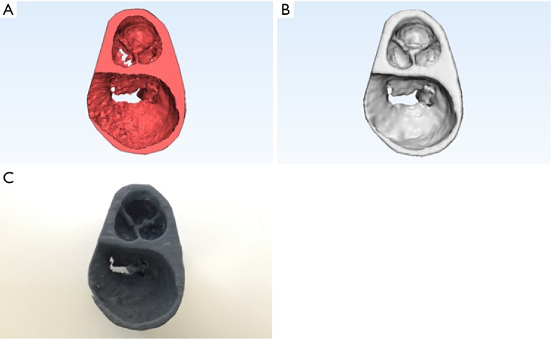
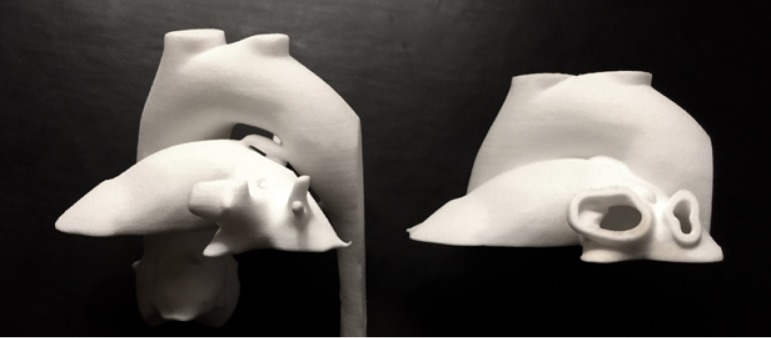
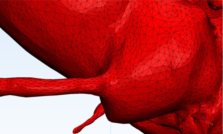
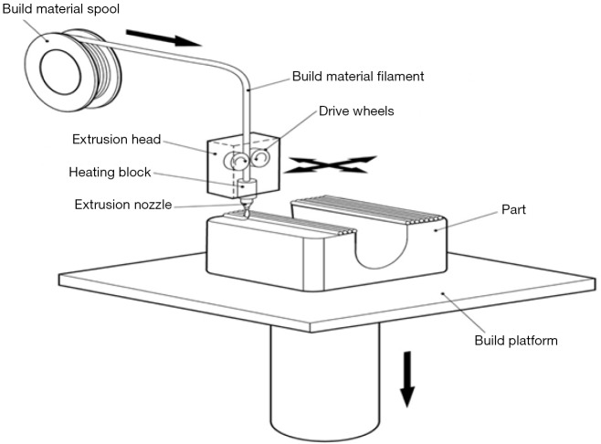
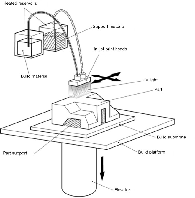
Current cardiovascular imaging techniques allow anatomical relationships and pathological conditions to be captured in three dimensions. Three-dimensional (3D) printing, or rapid prototyping, has also become readily available and made it possible to transform virtual reconstructions into physical 3D models. This technology has been utilised to demonstrate cardiovascular anatomy and disease in clinical, research and educational settings. In particular, 3D models have been generated from cardiovascular computed tomography (CT) imaging data for purposes such as surgical planning and teaching. This review summarises applications, limitations and practical steps required to create a 3D printed model from cardiovascular CT.

Keywords: 3D printing; Cardiovascular computed tomography (CT); Three-dimensional (3D) model.


Conflict of interest statement

Conflicts of Interest: The authors have no conflicts of interest to declare.

Figures

Figure 1
Figure 1
4D noise reduction. While noise and streak artifact varies across multiple phases, the underlying signal remains unchanged. Combination of multiple time points may therefore be used for noise reduction. (A) Original mesh; (B) mesh with partial de-noising; (C) mesh with full 4D de-noising. Images and STL files produced with Phyziodynamics, Ziosoft Software.
Figure 2
Figure 2
Volume-rendered (A) versus surface-rendered (B) image generated from cardiac CT. Volume rendered images are visually attractive but unusable for 3D printing. Surface rendered images approximate 3D printable files such as STL. Extensive processing may be required to select the region of interest and exclude artifacts.
Figure 3
Figure 3
Segmentation of the heart from cardiac CT. (A) Thresholding to capture anatomical structures, forming a mask; (B) cropping of the mask to restrict the region of interest to the left heart chambers.
Figure 4
Figure 4
Segmentation of the blood volume of the heart from cardiac CT. (A) Thresholding to capture the blood volume of the heart, forming a mask; (B) cropping of the mask to restrict the region of interest to the left heart chambers; (C) region growing to separate the blood volume of the left heart chambers from any surrounding structures.
Figure 5
Figure 5
Generation of a virtual 3D model from segmented cardiac CT imaging data. (A) Boolean subtraction to create a mask of the left heart chambers, excluding the blood volume; (B) resultant mask from Boolean subtraction; (C) calculation of a virtual 3D model from the resultant mask.
Figure 6
Figure 6
Generation of a 3D printed model. (A) Trimming of the 3D model to isolate the mitral valve apparatus, left ventricular cavity and aortic valve; (B) fixing holes in the geometry and cleaning the surface through wrapping and smoothing; (C) 3D printing of the model using vat polymerisation.
Figure 7
Figure 7
Powder bed fusion 3D print of a patent ductus arteriosus in an adult patient. Left Blood pool, right “Shell print” illustrating aortic and pulmonary and aortic artery walls.
Figure 8
Figure 8
STL (stereolithography, “standard tessellation language”) file. This common file format stores multiple triangle vertices, displaying the 3D surface as a collection of triangles or facets.
Figure 9
Figure 9
Superior and lateral views of 3D prints of the mitral valve apparatus and aortic valve. (A) and (B) material extrusion 3D print; (C) and (D) vat polymerisation 3D print. (E) and (F) powder bed fusion 3D print; (G) and (H) material jetting 3D print. Material extrusion and material jetting technology use a nozzle or jet to lay down a liquefied print material, which then solidifies before a new layer is built. Vat polymerisation and powder bed fusion technology use a laser to fuse multiple layers of print material. [Note: calibration inset, 10 mm × 10 mm squares].
Figure 10
Figure 10
Material extrusion 3D printing. A spool of material (usually ABS or PLA) is fed by drive wheels into a heating block where the material melts. The liquefied material is extruded via a nozzle on to the build plate or underlying layers of the nozzle. Each layer of the model solidifies as it cools post-extrusion, building the solid model layer by later. Image courtesy Victor Chang Cardiac Research Institute.
Figure 11
Figure 11
Material extrusion 3D print of the mitral valve apparatus. (A) and (B) Model with supports (in white); (C) and (D) model without supports after being placed in a water-based solution to dissolve the supports.
Figure 12
Figure 12
Vat polymerisation 3D printing. A laser or projected light source is selectively directed at a vat of photopolymer. Where the photopolymer is illuminated, it solidifies. Partially formed model is pulled upwards allowing new layers to be hardened by the light source. Image courtesy Victor Chang Cardiac Research Institute.
Figure 13
Figure 13
Powder bed fusion 3D printing. A bed of particulate material is heated to near its melting point. A laser is then used to selectively melt (sinter) areas of the powder material so that it forms a solid. A roller is used spread a thin layer of particulate matter of the partially formed model. The next layer is sintered onto the underlying method by the same laser heating process. Image courtesy Victor Chang Cardiac Research Institute.
Figure 14
Figure 14
Binder jetting 3D printing. A print head capable of emitting glue passes over a bed of particulate matter, conglomerating selected areas of the powder. A roller places a thin layer of powder over the partially formed model so that further adherent layers can be layed down. A colour print head can also be incorporated so that the exterior of the model is coloured with an emitted combination of coloured dyes. Image courtesy Victor Chang Cardiac Research Institute.
Figure 15
Figure 15
Material jetting 3D printing. Small print heads emit droplets of photopolymer which may have different colours or material properties. An ultraviolet light source cures each layer to harden it before liquid photopolymer is placed again, to form the next printed layer. Image courtesy Victor Chang Cardiac Research Institute.
Figure 16
Figure 16
Paediatric patient with a large ventricular septal defect (VSD) referred for repair surgery. From conventional imaging it was unclear whether to proceed with closing the defect, so 3D printing from gated cardiac CT was used for visualisation. Repair surgery was planned using the 3D printed model and closure of the defect was performed successfully. (A) and (B) 3D mesh demonstrating the VSD generated from gated cardiac CT. (C) and (D) 3D printed model of the VSD used for surgical planning.
Figure 17
Figure 17
Patient with a double outlet right ventricle (DORV), atrioventricular septal defect (AVSD) and sub-pulmonic stenosis referred for evaluation of suitability for biventricular repair. The procedure was deemed suitable following 3D visualisation and the patient underwent successful surgical repair. (A) 3D mesh demonstrating the DORV; (B) 3D mesh demonstrating the AVSD; (C) 3D printed model demonstrating the AVSD.
Figure 18
Figure 18
Superior and lateral views of part comparison analysis of mitral valve apparatus and aortic valve 3D models. The scale indicates the distance in millimetres between the CT scanned 3D prints and the source STL file. (A) and (B) Material extrusion 3D model; (C) and (D) vat polymerisation 3D model; (E) and (F) powder bed fusion 3D model; (G) and (H) material jetting 3D model. Material extrusion and material jetting technology use a nozzle or jet to lay down a liquefied print material, which then solidifies before a new layer is built. Vat polymerisation and powder bed fusion technology use a laser to fuse multiple layers of print material.

References

    1. Lee JW, Lee G, Lee NK, et al. Effectiveness of Adaptive Statistical Iterative Reconstruction for 64-Slice Dual-Energy Computed Tomography Pulmonary Angiography in Patients With a Reduced Iodine Load: Comparison With Standard Computed Tomography Pulmonary Angiography. J Comput Assist Tomogr 2016;40:777-83. 10.1097/RCT.0000000000000443 - DOI - PubMed
    1. Ryu YJ, Choi YH, Cheon JE, et al. Knowledge-based iterative model reconstruction: comparative image quality and radiation dose with a pediatric computed tomography phantom. Pediatr Radiol 2016;46:303-15. 10.1007/s00247-015-3486-6 - DOI - PubMed
    1. Otton JM, Kühl JT, Kofoed KF, et al. Four-dimensional image processing of myocardial CT perfusion for improved image quality and noise reduction. J Cardiovasc Comput Tomogr 2013;7:110-6. 10.1016/j.jcct.2013.01.014 - DOI - PubMed
    1. Nishii T, Kono AK, Tani W, et al. Four-dimensional noise reduction using the time series of medical computed tomography datasets with short interval times: a static-phantom study. PeerJ 2016;4:e1680. 10.7717/peerj.1680 - DOI - PMC - PubMed
    1. Tandon A, Byrne N, Nieves Velasco Forte Mde L, et al. Use of a semi-automated cardiac segmentation tool improves reproducibility and speed of segmentation of contaminated right heart magnetic resonance angiography. Int J Cardiovasc Imaging 2016;32:1273-9. 10.1007/s10554-016-0906-0 - DOI - PMC - PubMed

LinkOut - more resources