. 2017 Dec 21;7(1):18036.
doi: 10.1038/s41598-017-18363-1.

New Types of Experiments Reveal that a Neuron Functions as Multiple Independent Threshold Units

Affiliations

New Types of Experiments Reveal that a Neuron Functions as Multiple Independent Threshold Units

Shira Sardi et al. Sci Rep. .

Abstract

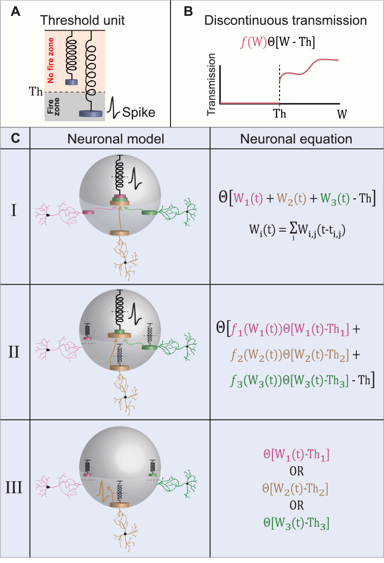
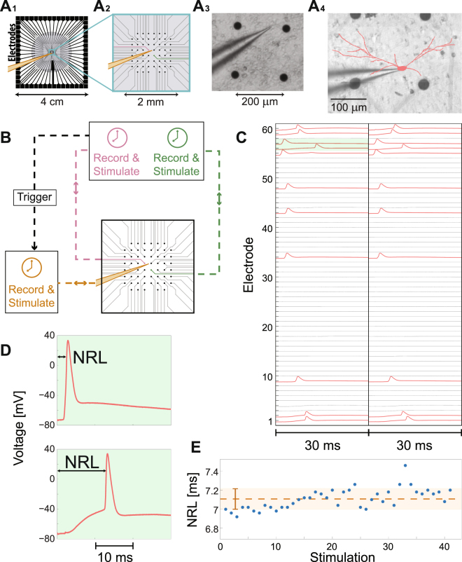
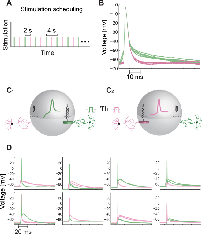
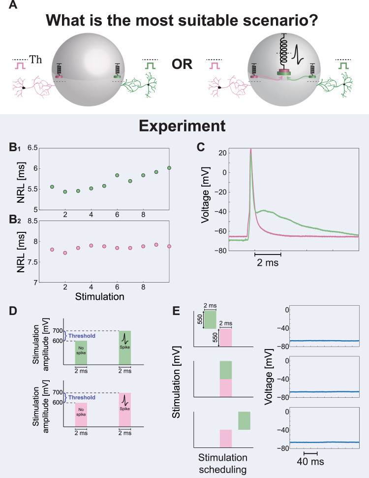
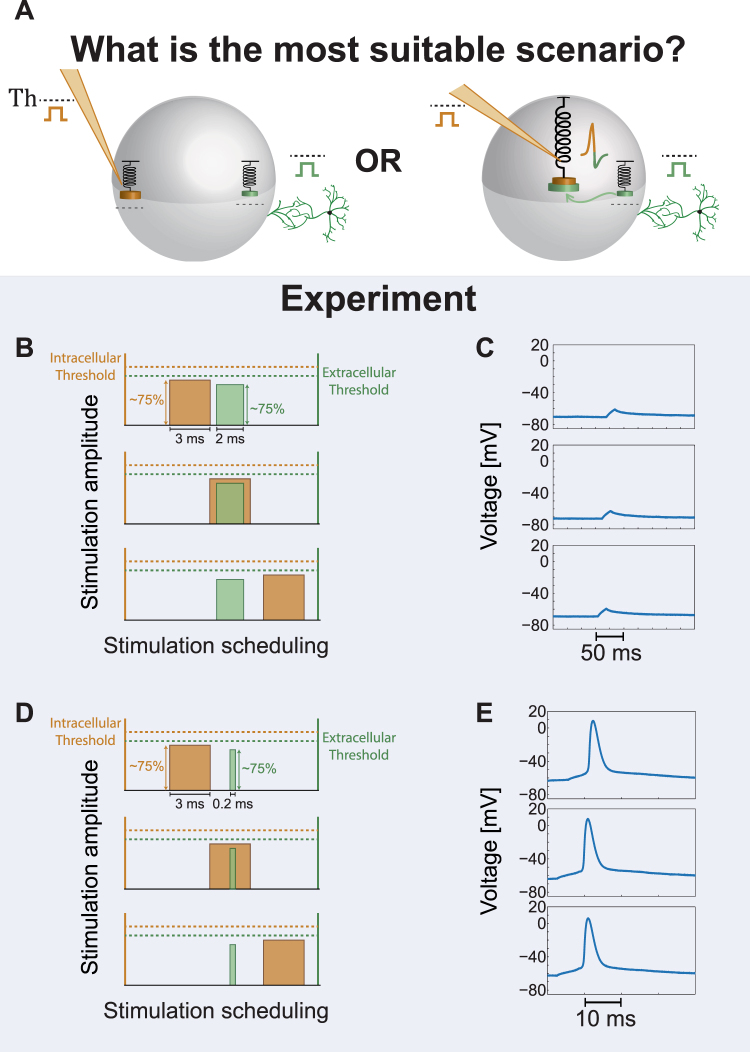
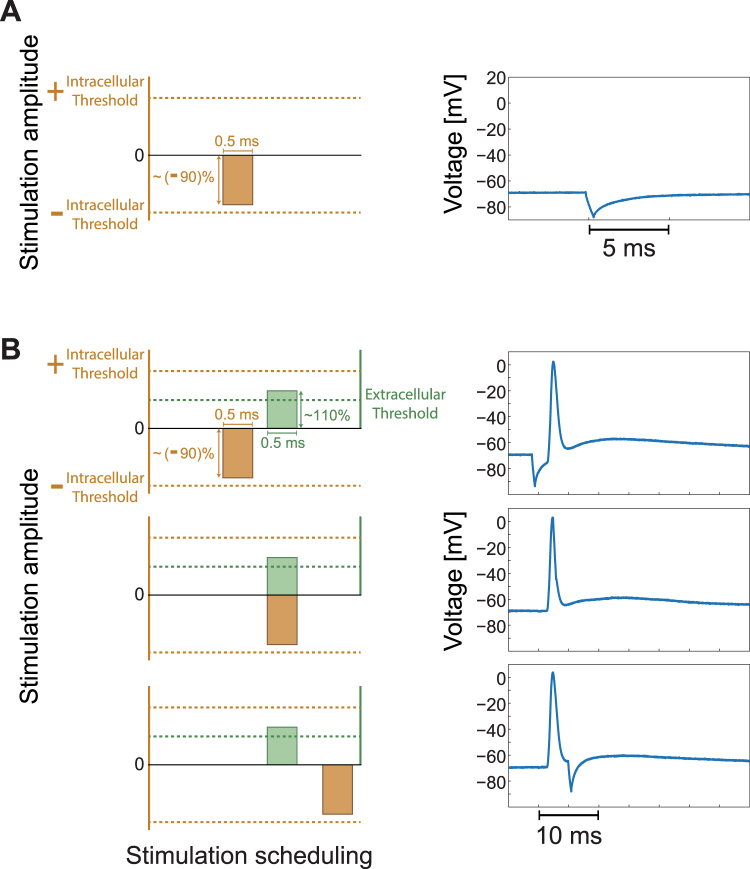
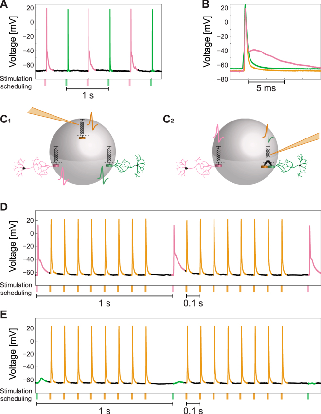
Neurons are the computational elements that compose the brain and their fundamental principles of activity are known for decades. According to the long-lasting computational scheme, each neuron sums the incoming electrical signals via its dendrites and when the membrane potential reaches a certain threshold the neuron typically generates a spike to its axon. Here we present three types of experiments, using neuronal cultures, indicating that each neuron functions as a collection of independent threshold units. The neuron is anisotropically activated following the origin of the arriving signals to the membrane, via its dendritic trees. The first type of experiments demonstrates that a single neuron's spike waveform typically varies as a function of the stimulation location. The second type reveals that spatial summation is absent for extracellular stimulations from different directions. The third type indicates that spatial summation and subtraction are not achieved when combining intra- and extra- cellular stimulations, as well as for nonlocal time interference, where the precise timings of the stimulations are irrelevant. Results call to re-examine neuronal functionalities beyond the traditional framework, and the advanced computational capabilities and dynamical properties of such complex systems.


Conflict of interest statement

The authors declare that they have no competing interests.

Figures

Figure 1
Figure 1
Models for a Neuron Functioning as an Excitable Threshold Element. (A) A threshold unit is represented by a spring and the load on the spring represents the incoming signal to the threshold unit. If the load is sufficient, the spring stretches and crosses the threshold, Th, represented by the dashed horizontal line, which results in an evoked spike. (B) A scheme demonstrating a discontinuous transmission function of the incoming signal, W. The transmission is zero below the threshold, Th, where it jumps discontinuously and follows a nonlinear function represented by f(W). (C) A table showing three possible neuronal computation models and their corresponding neuronal activation equations. (Model I) A neuron (represented by the gray sphere) consists of a unique centralized excitable mechanism, represented by the central spring. The load of the spring consists of a linear sum of the incoming signals from all the dendrites connected to the neuron (three colored dendrites and corresponding three colored weights in this illustration). The incoming (loaded) signals, represented by the three colored arrows and weights, stretch the spring and if a threshold crossing occurs (stretching beyond the dashed horizontal line) an evoked spike is generated. The quantitative function of the input-output relation of the neuron is presented in the right column, where Wi(t) stands for the accumulated input at time t of the ith dendrite (or a bunch of dendrites, see text), which is a weighted function, Wi,j(t − ti,j), of all the spikes, j, from the presynaptic neurons at preceding times, ti,j. (Model II) Similar to the first model, a neuron consists of a unique centralized excitable mechanism, represented by the central spring, however, there is also a spring associated with each dendrite, indicating that a dendrite transmits its signal to the central spring in a nonlinear manner only if a threshold crossing occurs (yellow and green dendrites, but not the pink one). The spring associated with each dendrite is characterized by its own threshold, Thi, and a nonlinear transfer function above Thi, fi(Wi(t)), represented by modified weights on the central spring. The functioning of the central excitable spring is identical to the first model (see neuronal equation on the right column and (B)). Note that the spring associated with each dendrite represents a threshold element for the signal transferring, but does not generate a spike as the central excitable spring. (Model III) There is no central excitable spring, but rather independent excitable springs associated with each dendrite, each one with its own threshold, Thi. If the incoming signal to a dendrite (or a bunch of coupled dendrites, see text) is above its threshold, an evoked spike is generated (yellow spike associated with the yellow dendrite).
Figure 2
Figure 2
The Experimental Setup and Principles of Measurements. (A) A micro-electrode array (MEA) consisting of 60 electrodes (see Methods for details). (A1) The gray circle with a diameter of ~2.2 cm represents the tissue culture area of ~1.3 million cortical neurons (Methods). (A2) Zoom-in of the blue square in (A1) showing the arrangement of the 60 extracellular electrodes, separated by 200 µm. A patched neuron, indicated by a yellow intracellular electrode, and two nearby extracellular electrodes (pink and green) are demonstrated. (A3) A snapshot of a section of a neuronal culture with an intracellular patch electrode and four extracellular electrodes, similar to (A2), allowing simultaneously recording and multiple stimulations. (A4) A reconstruction of a fluorescence image (Methods) of a patched neuron and its dendrites (red), growing to different directions. The typical distance to the nearest extracellular electrode (black circles) is much less than 100 µm. (B) A simplified scheme of the experimental setup according to A2 (see Methods and Supplementary Fig. S1 for more details). The extracellular and the intracellular electrodes are capable of recording and stimulating simultaneously in a time resolution of 20 μs using their controlled unit (color-coded). A trigger from the extracellular electrodes to the control unit of the intracellular electrode is used to synchronize their clocks. (C) An example of the developed experimental method for finding a subset of extracellular electrodes which reliably generate evoked spikes measured by the intracellular electrode. The 60 extracellular electrodes are stimulated serially at 2 Hz and above-threshold, where each electrode is stimulated several times (twice in this demonstration) and the voltage of the first 30 ms after each stimulation is presented. Red electrodes in the raster plot indicate electrodes which result in reliable evoked spikes. (D) A zoom-in of the green area in (C), presenting evoked spikes originated from 2 different extracellular stimulating electrodes. The neuronal response latency (NRL), measuring the time-lag between the extracellular stimulation and the intracellularly recorded evoked spike (measured following threshold crossing, see Methods), is exemplified. The NRL of the same neuron varies among extracellular stimulating electrodes; however, for a given stimulating electrode it is reproducible (for low stimulation frequencies), as can be qualitatively seen in (C). (E) The stability of the NRL is quantitatively demonstrated for 40 consecutive stimulations from a given electrode at 1 Hz. The orange dashed line represents the average NRL, and the orange bar (and light-orange area) represents the standard deviation, ~0.1 ms. See also Supplementary Fig. S1.
Figure 3
Figure 3
Variability in the Spike Waveform as a function of the Stimulation Location. (A) The alternating stimulation scheduling for this type of experiments. The patch neuron is alternatingly stimulated by two extracellular electrodes (green and pink, see also Fig. 2A2) at a low frequency, 0.5 Hz. Each colored rectangle represents a stimulation by the corresponding extracellular electrode (the width is arbitrary, see Methods for details), similar to the realization illustrated in Fig. 2A2. (B) An example of intracellular recording from a patch neuron stimulated alternatingly, as in (A), showing two different well-separated spike waveforms. The voltage is presented from 5 milliseconds prior to the threshold crossing, which is defined at -50 mV. (C) An illustration of a neuron stimulated above-threshold either via the green dendrite (C1) or via the pink dendrite (C2), where each one generates a different waveform for the spike (colored coded). The suitable neuronal model for the presented experimental results is model III in Fig. 1C, where when the green weight crosses its spring threshold a “green” spike is evoked, while when the pink weight crosses its spring threshold a “pink” spike is evoked. (D) Examples of different spike waveforms recorded intracellularly and generated by two extracellular stimulating electrodes (pink and green) with reliable evoked spikes (Fig. 2C). Each one of the eight panels is associated with a different neuron, and for each two electrodes two evoked spikes are plotted to illustrate the reproducibility of the spike waveform.
Figure 4
Figure 4
The Absence of Spatial Summation in Simultaneous Stimulations from Two Different Sources. (A) Possible scenarios for a neuronal computational model, where the neuron is simultaneously stimulated by two sub-threshold stimulations arriving from two extracellular electrodes. The amplitude of each sub-threshold stimulation is significantly above one half of its threshold. Left scenario demonstrates the lack of spatial summation, where each dendrite is coupled to an independent threshold mechanism. Although the sum of the two signals is above-threshold an evoked spike is absent (Model III in Fig. 1C). The right scenario presents a spike generated by the central threshold mechanism which sums all incoming signals (Model I or II in Fig. 1C). (B) The measured NRL for the two extracellular electrodes (green/pink in B1/B2), showing the stability of the NRLs around a different value for each one of the extracellular electrodes. (C) Intracellular recordings of the spike waveforms for the green and the pink extracellular electrodes (similar to Fig. 2A2) when stimulated above-threshold. The distinct different spike waveforms are visible. (D) The threshold of each one of the two electrodes was estimated using stimulation pattern of 2 ms duration and varied amplitudes (see Methods). For both electrodes reliable evoked spikes were observed at an amplitude of 800 mV, where at an amplitude of 500 mV no evoked spikes were observed. Hence, the threshold is in the range of (500, 800) mV and a stimulation of 500 mV is significantly above a half of the threshold. (E) The neuron is stimulated by the two extracellular electrodes, using a stimulation patterns of 2 ms as in (D) and 550 mV (~0.8 of the threshold, Th, of each electrode), and recorded intracellularly. Based on the prior knowledge of the NRLs in (B), the time-lags between the two stimulations were dynamically adjusted by relatively shifting the stimulation timings of the green electrode (see Methods). Specifically, the green stimulation was adjusted from a partial overlap with the pink stimulation, to a complete overlap and finally to non-overlapping timings (left). All scenarios did not result in evoked spikes, but in a negligible local depolarization independent of the relative timings between the two extracellular stimulations (right).
Figure 5
Figure 5
The Absence of Spatial Summation in Simultaneous Intracellular and Extracellular Stimulations. (A) Possible scenarios for a neuronal computational model, where the neuron is simultaneously stimulated by two sub-threshold stimulations, one arriving from an extracellular electrode (green) and the second from an intracellular electrode (orange). The sum of the two sub-threshold stimulations is significantly above the threshold. Left scenario demonstrates the lack of spatial summation, where each dendrite is coupled to an independent threshold mechanism (Model III in Fig. 1C). The right scenario presents a spike (combined colors) generated by the central threshold mechanism which sums all incoming signals (Model I or II in Fig. 1C). (B) The scheme of the performed experiment. Orange and green rectangles represent the stimulations from the intracellular electrode, 3 ms duration, and the extracellular electrode, 2 ms duration, respectively. Both stimulations are sub-threshold, ~75% of their threshold, as demonstrated by their relative amplitude in comparison to their threshold (dashed orange and green lines). The stimulation scheduling of the intracellular stimulation (orange) was shifted successively by 0.5 ms relative to the timing of the extracellular stimulation (where the NRL is omitted, green). Three possible scenarios between the two stimulations (partial overlapping, overlapping or non-overlapping) are illustrated. (C) The intracellular recorded voltage from the neuron according to the three scenarios in (B). All three scenarios exemplify similar shallow local depolarization and without an evoked spike, indicating the absence of summation of the intra- and the extra- cellular stimulations. (D) The scheme of the performed experiment, similar to (C), but the duration of the extracellular stimulation is 0.2 ms, since the patched neuron was close to the stimulating electrode (see Methods). Nevertheless, the stimulation was extracellular, since as the stimulation frequency was enhanced an increase in the NRL and in its fluctuations around an average value were observed (Supplementary Fig. S4). (E) A rare counter example, where the intracellular and the extracellular stimulations are summing up, both spatially and temporally. This behavior represents rare events, following our experimental evidence, and probably requires that the intra- and the extra- cellular spike waveforms will be identical (Supplementary Fig. S3), i.e. generated by the same local threshold mechanism. See also Supplementary Figs. S2–S4.
Figure 6
Figure 6
The Absence of Spatial Subtraction in Simultaneous Intracellular and Extracellular Stimulations. (A) Left: The intracellular threshold amplitude is represented by the upper dashed horizontal orange line and correspondingly the minus threshold amplitude, the lower dashed orange line. An intracellular stimulation with a duration of 0.5 ms and an amplitude of approximately -90% of the threshold amplitude is represented. Right: A temporary drop of several ms in the membrane voltage by such a short pulse with a negative amplitude (left) is presented. (B) Left: A neuron is simultaneously stimulated by a slightly above-threshold extracellular stimulation, a duration of 0.5 ms and an amplitude of 110% of the threshold (green), and by a negative intracellular amplitude slightly above the minus amplitude of the threshold as in (A) (orange). The relative timing between these two stimulations was tuned by shifting the timing of the intracellular stimulation by 0.5 ms every three pairs of such intra- and extra- cellular stimulations (see Methods). Three possible scenarios are presented (upper/middle/lower panels), where the extracellular stimulation, with the exclusion of the NRL, is slightly before/ at the same time/ after the intracellular stimulation. Right: An evoked spike is recorded for all three scenarios, indicating that there is no subtraction between the two stimulations.
Figure 7
Figure 7
Non-Overlapping Time-Dependent Extra- and Intra- Cellular Stimulations Induce Interference in the Spiking Activity. (A) Intracellular recordings of a neuron stimulated alternately at 2 Hz by two extracellular electrodes (green and pink) with reliable evoked spikes. (B) The spike waveforms generated by the stimulations of the two extracellular electrodes (green and pink) and by an intracellular stimulation (orange). It is evident that the green and the orange waveforms are very similar, whereas the pink waveform is different. (C) Two possible scenarios for the spike generation. (C1): The neuron consists of three threshold elements associated with intracellular stimulations and with each one of the two extracellular stimulation locations, represented by different spike colors. (C2): The intracellular stimulation and the green extracellular stimulation activate the same sub-neuronal threshold element, represented by the two springs connected to the threshold spring and by a two-color spike. (D) Recorded spike train with the stimulating scheduling. The pink extracellular electrode was stimulated every 1 s and in between 8 intracellular stimulations were given separated by ~100 ms. The spike color is associated with the origin of the corresponding type of the stimulation. The duration/amplitude was 2 ms/800 mV for an extracellular stimulation and 3 ms/600 pA for an intracellular stimulation. (E) Similar to (D), but with the stimulation of the green extracellular electrode results in response failures. See also Supplementary Figs S5,S6.

Similar articles

Cited by

References

    1. Anderson J, Binzegger T, Kahana O, Martin K, Segev I. Dendritic asymmetry cannot account for directional responses of neurons in visual cortex. Nature neuroscience. 1999;2:820–824. doi: 10.1038/12194. - DOI - PubMed
    1. Euler T, Detwiler PB, Denk W. Directionally selective calcium signals in dendrites of starburst amacrine cells. Nature. 2002;418:845–852. doi: 10.1038/nature00931. - DOI - PubMed
    1. Gasparini S, Migliore M, Magee JC. On the initiation and propagation of dendritic spikes in CA1 pyramidal neurons. Journal of Neuroscience. 2004;24:11046–11056. doi: 10.1523/JNEUROSCI.2520-04.2004. - DOI - PMC - PubMed
    1. Cai X, et al. Unique roles of SK and Kv4. 2 potassium channels in dendritic integration. Neuron. 2004;44:351–364. doi: 10.1016/j.neuron.2004.09.026. - DOI - PubMed
    1. Branco T, Häusser M. The single dendritic branch as a fundamental functional unit in the nervous system. Current opinion in neurobiology. 2010;20:494–502. doi: 10.1016/j.conb.2010.07.009. - DOI - PubMed

Publication types

LinkOut - more resources