. 2018 Jan 30;18(3):451-462.
doi: 10.1039/c7lc00724h.

Razor-printed sticker microdevices for cell-based applications

Affiliations

Razor-printed sticker microdevices for cell-based applications

Loren E Stallcop et al. Lab Chip. .

Abstract

Tape-based razor-printing is a flexible and affordable ultra-rapid prototyping approach for microscale device fabrication. However, integration of this prototyping approach into cell-based assay development has been limited to proof of principle demonstrations. This is in large part due to lack of an established or well-characterized option for biocompatible adhesive tape. Without such an option, integration of these areas will remain unexplored. Therefore, to address this critical hurdle, we characterized microscale devices made using a potentially biocompatible double-sided adhesive, ARCare 90106. We validated tape-based device performance against 96-well plates and PDMS microdevices with respect to cell viability, hydrophobic small molecule sequestration, the potential for leaching compounds, use in fluorescence microscopy, and outgassing (bubble formation). Results supported the tape as a promising tool for future cell-based assay development. Therefore, we subsequently demonstrated specific strengths enabled by the ultra-rapid (<1 h per prototype) and affordable (∼$1200 cutting plotter, <$0.05 per prototype) approach. Specifically, data demonstrate the ability to integrate disparate materials for advanced sticker-device functionality such as bonding of polystyrene devices to glass substrates for microscopy applications, inclusion of membranes, and incorporation of different electrospun biomaterials into a single device. Likewise, the approach allowed rapid adoption by uninitiated users. Overall, this study provides a necessary and unique contribution to the largely separate fields of tape-based razor-printing and cell-based microscale assay development by addressing a critical barrier to widespread integration and adoption while also demonstrating the potential for new and future applications.


Figures

Figure 1
Figure 1. Tape-based razor-printing fabrication of microscale sticker devices
(A) Automated cutting plotter based on printer technology allows razor-printing (xurography) for precisely cutting shapes from sheets of material. (B) Example of a cuttable laminate formed by marrying a polymer sheet (e.g., PS) and a sheet of double sided adhesive tape. (C) The razor of the cutting plotter cuts through the laminate to create device components. (D) Cut components are layered to form devices and 3D structures that can be applied like a sticker to a wide variety of substrates. (E) Example of a razor-printed co-culture sticker device fabricated using PS-Tape laminate, cell seeding procedure, and nomenclature of different device regions.
Figure 2
Figure 2. Nested co-culture device design and construction
Photos of devices fabricated with four techniques and cross-sectional schematic of the device components. Manufacturer thicknesses of PS sheeting and Tape are 0.05 mm and 0.143 mm, respectively. (A) Device constructed from PDMS using soft lithography. (B) Device constructed using micromilled PS and razor-printed double-sided biomedical adhesive tape. (C) Razor-printed PS-Tape laminate device. (D) Razor-printed PDMS device. (solid white lines) 10 mm scale bar. (dashed red lines) region of the cross-section schematic.
Figure 3
Figure 3. Cell viability, morphology, and device absorption of lipophilic molecules
(A) Cell viability at 24 hrs by cell type (MCF-7, LNCaP, or RPMI 8226) and device construction (96-well plate, Milled PS + tape, PS-Tape laminate, or PDMS soft-lithography) in 2D culture. (B) Images of nile red adsorbed/absorbed to/in a PS-Tape and PDMS device. (C) Graph of estradiol (E2) dose-response curves for MVLN ERE luciferase reporter cell line in PS-Tape and PDMS co-culture devices. (D) MDA-MB-468 and MDA-MB-231 were mono-cultured in 96-well plates and co-culture devices made of PDMS or razor-cut PS-Tape using low serum DMEM culture medium or no-phenol DMEM with charcoal stripped serum (stripped) for 96 hrs. AldeRed was used to quantify the % of total cells with high levels of the stem cell marker ALDH1 (ALDH1 HI ). (E) Cell morphology of HMF cells cultured in different device types. Brightfield and nuclear stained images are thresholded and overlaid to show regions of cytoplasm (gray) and nuclei (blue) to aid comparison. Images of other cells types (LNCaP, MDA-MB-231, and RPMI 8226) are contained in Fig S3. PDMS-Plasma refers to a PDMS device in which the glass culture substrate was pretreated via oxygen plasma treatment. (F) Plot of average equivalent cell radius for each cell type in each culture device type (*≤ 0.05, **≤ 0.01, t-test, two-tailed, Bonferroni correction, error-bars indicate std. dev.).
Figure 4
Figure 4. Analysis of tape fluorescence and demonstration of immunofluorescence staining
(A) Tape fluorescence measured using a Nanodrop 3300 fluorospectrometer (Thermo Scientific) using the UV excitation mode (355–375 nm) or white light excitation mode (460–650 nm). (B) LNCaP cells were stained using DAPI nuclear stain (top-right) and anti-EpCAM (epithelial cell adhesion molecule) fluorescent antibody (bottom-right). (left) False colored and magnified overlay of nuclear labeling (blue) and expression of the cell membrane protein EpCAM (red). Grayscale images have an intensity range of 0–255 units. Tape fluorescence outside the culture well was ~22 units for 390/440 nm and ~1 unit for 648/684 nm.
Figure 5
Figure 5. Bubble Formation in Tape Channels
Microchannels were cut into Tape and overlaid with a razor-printed PS port layer and placed onto either untreated glass (Glass) or tissue culture polystyrene (TCP) and filled with culture media containing 10% fetal bovine serum. Tape treatment (Tape Tx) conditions consisted of sonicating the tape layer alone for 30 min in either a 1% Pluronic F-127 solution in PBS (Plur.) or DI H2O (H2O), while hot plate treatment (Hot Plate Tx) conditions consisted of incubating the assembled channel at 60°C for 2hrs in either a dry Petri dish (Dry) or dish containing 1 mL DI H2O and sealed with parafilm (Humid). (A) Quantification of spontaneous bubble formation after 2 days incubation at 37°C. Each of the Glass and Hot Plate-treated TCP conditions were significantly different than the non-Hot Plate-treated TCP conditions (p < 0.001), and the [TCP,Plur.,—] condition was significantly different than both the [TCP,—,—] and [TCP, H2O, —] conditions (p < 0.05). Significance not shown in figure for readability, and n = 10 technical replicates. (B) Brightfield microscopy images (2X) of the quantified conditions in (A), using the notation [<Substrate>, <Tape Tx>, <Hot Plate Tx>]. No treatment is denoted with an em dash (—).
Figure 6
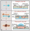
Figure 6. Rapid prototyping of 3 different cell culture assay designs
Images and schematics illustrate device construction. The schematics to the right of the images depict cross-section views of each device at the red dashed line.
Figure 7
Figure 7. Razor-printing and patterning of electrospun collagen sheets
(A) Processing of electrospun collagen sheets for patterning via razor-printing. (i) Bonding of collagen sheet to ARcare 90106 exposed surface. (ii) Collagen/Tape sheet for use in automated plotter cutter. (iii) Automated cutting of the geometric pattern through collagen/Tape sheet. (iv) Collect pieces cut-out from collagen/Tape sheet and peel-off back layer for binding on TCP or glass surface (v). (B) Prototype of a PS microwell array containing adjacent microwells with 3 different culture surfaces: TCP (I), aligned collagen fibers (II) and randomly- oriented collagen fibers (III). POA = prevalent orientation angle and OI = orientation indices (a measure of angle variability) and NOI = normalized orientation index (0% or 100%=aligned, 50%=random).

References

    1. Martínez-López JI, Mojica M, Rodríguez CA, Siller HR. Xurography as a Rapid Fabrication Alternative for Point-of-Care Devices: Assessment of Passive Micromixers. Sensors. 2016;16 - PMC - PubMed
    1. Cosson S, Aeberli LG, Brandenberg N, Lutolf MP. Ultra-rapid prototyping of flexible, multi-layered microfluidic devices via razor writing. Lab Chip. 2014;15:72–76. - PubMed
    1. de Santana PP, de Oliveira IMF, Piccin E. Evaluation of using xurography as a new technique for the fabrication of disposable gold electrodes with highly reproducible areas. Electrochem commun. 2012;16:96–99.
    1. Greer J, Sundberg SO, Wittwer CT, Gale BK. Comparison of glass etching to xurography prototyping of microfluidic channels for DNA melting analysis. J Micromech Microeng. 2007;17:2407–2413.
    1. Renaud L, Selloum D, Tingry S. Xurography for 2D and multi-level glucose/O2 microfluidic biofuel cell. Microfluid Nanofluidics. 2015;18:1407–1416.

Publication types

LinkOut - more resources