. 2018 Mar;46(3):377-391.
doi: 10.1007/s10439-017-1976-4. Epub 2018 Jan 11.

Biomechanical Characterisation of Bone-anchored Implant Systems for Amputation Limb Prostheses: A Systematic Review

Affiliations

Biomechanical Characterisation of Bone-anchored Implant Systems for Amputation Limb Prostheses: A Systematic Review

Alexander Thesleff et al. Ann Biomed Eng. 2018 Mar.

Abstract

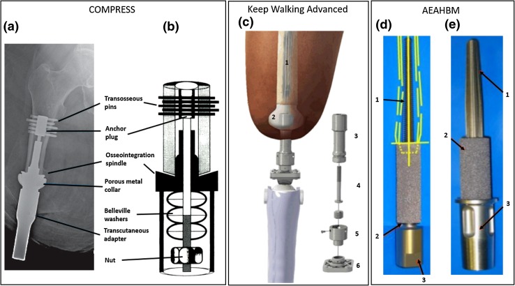
Bone-anchored limb prostheses allow for the direct transfer of external loads from the prosthesis to the skeleton, eliminating the need for a socket and the associated problems of poor fit, discomfort, and limited range of movement. A percutaneous implant system for direct skeletal attachment of an external limb must provide a long-term, mechanically stable interface to the bone, along with an infection barrier to the external environment. In addition, the mechanical integrity of the implant system and bone must be preserved despite constant stresses induced by the limb prosthesis. Three different percutaneous implant systems for direct skeletal attachment of external limb prostheses are currently clinically available and a few others are under investigation in human subjects. These systems employ different strategies and have undergone design changes with a view to fulfilling the aforementioned requirements. This review summarises such strategies and design changes, providing an overview of the biomechanical characteristics of current percutaneous implant systems for direct skeletal attachment of amputation limb prostheses.

Keywords: Bone-anchored prostheses; Direct skeletal attachment; Osseointegration.


Figures

Figure 1
Figure 1
Schematic view of the methodology used for the literature review and the search results. From the filtered article search, the number of articles per implant system was determined according to the following criterion. In order to be counted as an article for a particular implant system, the article had to describe the mechanical properties of the implant system or report results from implantation of the implant system for direct skeletal attachment of a load-bearing artificial limb.
Figure 2
Figure 2
(a) Schematic image of OPRA implant system in an amputated limb; (b) OPRA Fixture; the exterior surface in the dark grey region is treated to enhance osseointegration. The lower image shows a close-up of the laser-induced micro structure from the surface treatment; (c) Schematic image of the ILP implant system: (1) Porous coated portion of the intramedullary component of the implant system, (2) inner lining, (3) Morse taper, (4) dual cone adapter, (5) knee connecting adapter. The red line indicates the stoma channel; (d) Close-up of the spongiosa metal surface to enhance osseointegration and ingrowth; (e) ILP implant system assembled; (f) Exploded view of ILP implant system assembly consisting of: (1) intramedullary implant, (2) temporary cover screw, (3) dual cone adapter, (4) safety screw, (5) sleeve, (6) rotating disc (until prosthetist has made final adjustments), (7) final propeller screw, (8) provisional screw; (g) OPL type-B implant system. Images A and B are published with courtesy of Integrum AB. Images C, D, E and F are reprinted from Journal of Rehabilitation Research & Development. Image G is reprinted from Unfallchirurg with permission from Springer.
Figure 3
Figure 3
Design changes over time for the ILP implant. (a) First ILP implant design. The material is medical-grade cobalt-chrome alloy. The implant has a rough surface on both the intramedullary region and the subdermal region. A bone-stabilising bracket for improved fatigue properties; (b) Second implant design. Rough surface on distal post and bracket removed. Bracket, distal portion of implant and connector reduced in size; (c) Third implant design. Bracket removed. Revised connection to implant to a dual cone connection. Reprinted from Journal of Rehabilitation Research & Development.
Figure 4
Figure 4
Examples of available OPL implants. (a) OPL type A with distal niobium polished extramedullary head; (b) OPL type B with an intramedullary distal head; (c–e) Custom-made implants with macroporous 3D mesh coating for accelerated osseointegration. Reprinted from Unfallchirurg.
Figure 5
Figure 5
(a) Single-component POP implant used in sheep studies: (1) tapered smooth region, (2) fluted region, (3) porous coated region, (4) porous coated subdermal barrier, (5) Morse taper for connection to exo-prosthesis; (b) POP implant system assembly for humans: (1) implant stem, (2) stoma shield, (3) percutaneous post, (4) assembly bolt, (5) adapter, (6) adapter bolt; (c) Schematic view of the ITAP implant; (d) Radiograph of ITAP implant in a transhumeral amputee; (e) ITAP implant used in dog number 3 of the clinical study on dogs. Image A is reprinted from Clinical Orthopaedics and Related Research, with permission from Springer. Image B is reprinted from US Patent 9,433,505. Images C and D are reprinted from Journal of Hand Surgery with permission from Elsevier. Image E is reprinted from Veterinary Surgery with permission from John Wiley and Sons.
Figure 6
Figure 6
(a) Compress percutaneous device radiograph; (b) Schematic diagram of the Compress endoprosthetic implant, demonstrating Belleville washers stacked over a traction bar housed within the endoprosthetic taper at the bone-prosthetic interface; (c) Schematic view of the keep walking advanced implant system: (1) intramedullary rod, (2) spacer, (3) intermediate device, (4) locking screw, (5) upper connecting piece, (6) lower connecting piece; (d) AEAHBM implant original design; yellow lines represent the patient’s tibial shaft: (1) Tapered threaded stem of Ti6Al4 V, (2) base of porous tantalum sleeve, (3) Morse taper fitting for external prosthesis; (e) AEAHBM implant modified design: (1) Intramedullary stem of Ti6Al4 V with longitudinal splines, (2) porous tantalum sleeve, (3) external region of Ti6Al4 V implant. Image A has been adapted from Unfallchirurg with permission of Springer. Image B has been adapted from International Orthopaedics with permission of Springer. Image C is published from Rehabilitación with permission of the Publisher. Images D and E are reprinted from Veterinary Surgery with permission from John Wiley and Sons.

References

    1. Ahlers, O. Verfahren zur herstellung eines implantates mit einer seine oberfläche zumindest teilweise bedeckenden metallischen offenzelligen struktur. Patent: EP 0,502,349, 1995.
    1. Al Muderis, M. An osseointegrable device. Patent: US patent app. publ. 0,331,422, 2016, 2016.
    1. Al Muderis M, Aschoff HH, Bosley B, Raz G, Gerdesmeyer L, Burkett B. Direct skeletal attachment prosthesis for the amputee athlete: The unknown potential. Sport. Eng. 2016;19:141–145. doi: 10.1007/s12283-016-0196-8. - DOI
    1. Al Muderis M, Bosley BA, Florschutz AV, Lunseth PA, Tyler DK, Highsmith JM, Kahle JT. Radiographic assessment of extremity osseointegration for the amputee. Technol. Innov. 2016;18:211–216. doi: 10.21300/18.2-3.2016.211. - DOI - PMC - PubMed
    1. Al Muderis M, Khemka A, Lord SJ, Van de Meent H, Frölke JPM. Safety of osseointegrated implant for transfemoral amputees, a two-center prospective cohort study. J. Bone Jt. Surg. 2016;98:900–909. doi: 10.2106/JBJS.15.00808. - DOI - PubMed

Publication types