Review
. 2017 Dec 27;4(6):061508.
doi: 10.1063/1.4996505. eCollection 2017 Nov.

Charge migration and charge transfer in molecular systems

Affiliations
Review

Charge migration and charge transfer in molecular systems

Hans Jakob Wörner et al. Struct Dyn. .

Abstract

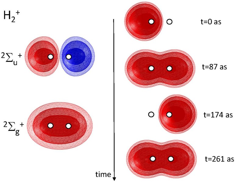
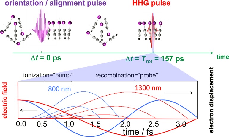
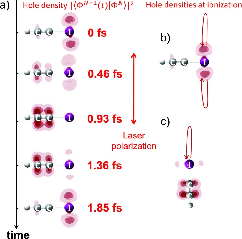
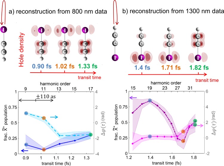
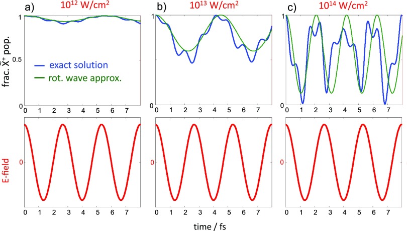
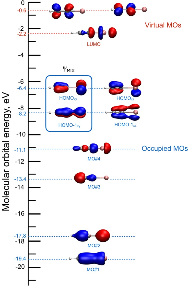
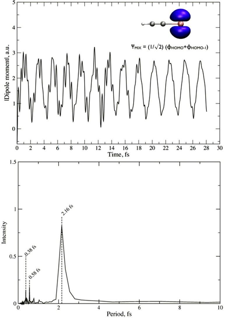
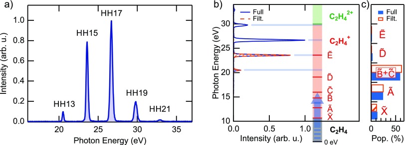
The transfer of charge at the molecular level plays a fundamental role in many areas of chemistry, physics, biology and materials science. Today, more than 60 years after the seminal work of R. A. Marcus, charge transfer is still a very active field of research. An important recent impetus comes from the ability to resolve ever faster temporal events, down to the attosecond time scale. Such a high temporal resolution now offers the possibility to unravel the most elementary quantum dynamics of both electrons and nuclei that participate in the complex process of charge transfer. This review covers recent research that addresses the following questions. Can we reconstruct the migration of charge across a molecule on the atomic length and electronic time scales? Can we use strong laser fields to control charge migration? Can we temporally resolve and understand intramolecular charge transfer in dissociative ionization of small molecules, in transition-metal complexes and in conjugated polymers? Can we tailor molecular systems towards specific charge-transfer processes? What are the time scales of the elementary steps of charge transfer in liquids and nanoparticles? Important new insights into each of these topics, obtained from state-of-the-art ultrafast spectroscopy and/or theoretical methods, are summarized in this review.


Figures

FIG. 1.
FIG. 1.
Electronic wavefunctions of the ground Σ2g+ and first electronically excited Σ2u+ states of H2+ (left) and time-dependent electron density following the preparation of the superposition state (Φg+Φu)/2 at t = 0 (right).
FIG. 2.
FIG. 2.
Concept of the experiment: The molecules are dynamically oriented using a two-color laser pulse. High harmonics are generated at the first full rotational period (upper panel). By selecting the short trajectories (thin lines, lower panel), a unique transit-time-to-energy mapping in the laser field (thick lines) is achieved. Changing the wavelength from 800 nm (blue) to 1300 nm (red) is equivalent to selecting a different window of excursion times for the continuum electron.
FIG. 3.
FIG. 3.
(a) The reconstructed electron-hole density is displayed as a function of time after strong-field ionization of HCCI molecules aligned perpendicular to the polarization of the driving laser pulse. The reconstructed hole densities at the time of ionization are also illustrated for molecules aligned perpendicular (b) or parallel (c) to the laser field.
FIG. 4.
FIG. 4.
Electron-hole densities for HCCI molecules aligned parallel to the polarization of the laser field reconstructed from high-harmonic emission driven by an 800-nm (a) or 1300-nm (b) driving laser field. The lower panels show the fractional populations of the X~+ state (left vertical axis: the time-dependent population of the A~+ state is given by normalization) and the relative phase between the X~+ and A~+ states (right vertical axis). Panels (a) and (b) illustrate the dynamics following ionization from the iodine and hydrogen sides, respectively.
FIG. 5.
FIG. 5.
(a)–(c) Fractional population of the electronic ground state of HCCI+, treated as a two-level system and aligned parallel to an 800-nm laser field of the indicated intensities. The blue line shows the exact solution of the time-dependent Schrödinger equation, whereas the green line is the solution for the rotating-wave approximation neglecting higher order frequencies in the population transfer. The time-dependent laser field is illustrated in the lower panels.
FIG. 6.
FIG. 6.
Canonical Kohn-Sham molecular orbital diagram of neutral HCCI. The orbitals involved in the superposition mixture are indicated by the square. All orbital contours are obtained using a 0.01 e/Å3 isovalue.
FIG. 7.
FIG. 7.
Upper panel: dipole moment oscillations of HCCI+ ionized from a HOMO/HOMO-1 superposition of states. In the upper right corner, the molecular orbital resulting from the linear combination is shown, ΨMIX, using a 0.01 e/Å3 isovalue. In the lower panel, the dipole moment oscillations are Fourier transformed to period-space.
FIG. 8.
FIG. 8.
(a) Full spectrum of harmonics used as a pump in the experiment. (b) Comparison between the photon energies and the vertical excitation to the main cationic states. (c) Population of the cationic states after excitation by the spectra shown in (b), calculated with the tabulated values for monochromatic excitation. As it is possible to observe, both the full spectrum (blue) and a filtered spectrum composed of only two harmonics (orange) can efficiently populate only the first four states of the molecular cation.
FIG. 9.
FIG. 9.
(a) Schematic drawing of the internal relaxation from an excited cation state to its ground state after XUV excitation. (b) An opportunely delayed IR pulse that can be used to stop the relaxation process by giving the molecule enough energy to lose one or two H atoms.
FIG. 10.
FIG. 10.
(a)–(c) IR-induced change of the ion yields for decreasing IR intensities in the probe pulse after excitation with the full harmonic spectrum of Fig. 8(a). (d) IR-induced changes for the case of excitation with the filtered spectrum composed of only two harmonics [Fig. 8(b)] and an IR intensity of 2.5 × 1012 W/cm2. The main features and their time constants are robust to the change in intensity and the XUV excitation spectrum. Adapted from the supplementary information of Ref. .
FIG. 11.
FIG. 11.
(a) Calculated population on the four lowest cationic states as a function of time after selective excitation to C~,B~ and A~ (top to bottom panels). Distribution of the C-H distances, (c), and dihedral angles, (d), of the hopping geometries for transitions between different PESs.
FIG. 12.
FIG. 12.
Time-resolved photoelectron spectra of aqueous ferricyanide upon photoexcitation of the LMCT band centred at 420 nm. The inset shows the static (unpumped) photoelectron spectra of water and aqueous ferro- and ferri-cyanide solutions in the region of the Fe2+∕3+ HOMO, easily distinguishing the oxidation state. Reproduced with permission from Ojeda et al., Phys. Chem. Chem. Phys. 19, 17052 (2017). Copyright 2017 The Royal Society of Chemistry and the PCCP Owner Societies.
FIG. 13.
FIG. 13.
Transient IR spectra upon 400 nm excitation of [Fe(CN)6]3+ in H2O (left), D2O (centre) and ethylene glycol (right). The spacings of the grids in the 2D representations correspond to various frequencies of the T1u CN-stretch mode in the electronic ground state. Reproduced with permission from Ojeda et al., Phys. Chem. Chem. Phys. 19, 17052 (2017). Copyright 2017 The Royal Society of Chemistry and the PCCP Owner Societies.
FIG. 14.
FIG. 14.
Schematic representation of the dynamics induced by LMCT excitation of ferric hexacyanide in solution. The sudden electron transfer to the metal triggers vibrational excitation of the CN ligands. The back electron transfer occurs in 500 fs leaving the molecule in a vibrationally hot state, with levels up to v =2 being populated. See Ref. for details.
FIG. 15.
FIG. 15.
(a) The molecular assembly used to accumulate two electrons in the central anthraquinone (AQ) in a light-driven process. The electron and proton transfer steps are indicated. (b) Verification of the quadratic power dependence of the doubly reduced state AQ2–. To that end, the amplitude of an IR band indicative of the doubly reduced state AQ2− at 1366 cm−1 is plotted against the bleach signal of AQ at 1322 cm−1. (c) Electron pathway of the doubly reduced state in an energy level scheme, with the time-scales of various electron and proton transfer steps indicated. The pathway with a single excitation leading to the singly reduced state is omitted for clarity. Adapted from Refs. and .
FIG. 16.
FIG. 16.
Schematic representation of the electron transfer and FRET processes between the two tryptophans (Trp) in myoglobin and porphyrin.
FIG. 17.
FIG. 17.
Left panel: Transient X-ray absorption spectra corresponding to the transition from the Co(II) to Co(I) state. Calculations for different models of Co(I) state: 5-coordinated model [red curve (1)], 4-coordinated model [black curve (2)] and 6-coordinated model with moderate out-of-plane displacement of Co and disordered solvent molecule [green curve (3)] are compared with the experimental data for the multicomponent photocatalytic system with the Co(dmgBF2)2 catalyst (blue curve 4). Central panel: Structural models used for the calculations. Grey atoms are C, Blue: N, Green: B, Yellow: F, Red: O, and Magenta: Co. H atoms are omitted for clarity. Right panel: Comparison of the experimental Co K-edge XANES spectra of cobaloxime in acetonitrile (black line on the top) with the theoretical simulation for the best-fit structure (red line on the top). Calculated transient XANES data for the best-fit model (red line, bottom) are compared with the experimental data (black line, bottom). Adapted with permission from Smolentsev et al., Faraday Discuss. 171, 259 (2014). Copyright 2014 The Royal Society of Chemistry, licensed under CC BY 3.021 and adapted with permission from G. Smolentsev and V. Sundstrom, Coord. Chem. Rev. 304305, 117 (2015). Copyright 2015 Elsevier.
FIG. 18.
FIG. 18.
Femtosecond fluorescence of aqueous iodide. (a) Fluorescence of 1 M NaI dissolved in water upon 266 nm excitation. The Raman signal from water was removed from the plot. (b) Normalized kinetic traces at different wavelengths with their representative fits (continuous lines), compared with the Raman signal from water at 293 nm, whose temporal width gives the instantaneous response function of the setup. Reprinted with permission from Messina et al., Nat. Commun. 4, 2119 (2013). Copyright 2013 Macmillan Publishers Ltd.
FIG. 19.
FIG. 19.
(Top) Above band-gap excitation of TiO2 nanoparticles leading to the trapping of charge carriers in the sub-surface region of the defect-rich shell. (Bottom) Excitation of the dye sensitizer leading to the trapping of the electron at the outer surface of the defect-rich shell.
FIG. 20.
FIG. 20.
(Left) Femtosecond optical pump/Ti K-edge X-ray absorption probe of bare TiO2 nanoparticles excited above the band gap. Reprinted with permission from Santomauro et al., Sci. Rep.-Uk. 5, 14834 (2015). Copyright 2015 Macmillan Publishers Ltd., licensed under CC BY 4.0. The time trace shows an ultrafast localization of the electron at a Ti atom in about 170 fs (red trace), but the large error bars imply a rise time of as long as 300 fs (grey trace). (Right) Schematic description of the electron trapping at pentacoordinated defects. The implication of the fs XAS result is that the electron is trapped at or in the immediate vicinity of the unit cell where it is created.

References

    1. May V. and Kühn O., Charge and Energy Transfer Dynamics in Molecular Systems ( John Wiley & Sons, 2011).
    1. Marcus R. A., J. Chem. Phys. 24, 966 (1956).10.1063/1.1742723 - DOI
    1. Marcus R. A., J. Chem. Phys. 24, 979 (1956).10.1063/1.1742724 - DOI
    1. Zewail A. H., J. Phys. Chem. A 104, 5660 (2000).10.1021/jp001460h - DOI
    1. Hentschel M., Kienberger R., Spielmann C., Reider G. A., Milosevic N., Brabec T., Corkum P., Heinzmann U., Drescher M., and Krausz F., Nature 414, 509 (2001).10.1038/35107000 - DOI - PubMed

LinkOut - more resources