A new class of magnetically actuated pumps and valves for microfluidic applications
- PMID: 29343852
- PMCID: PMC5772482
- DOI: 10.1038/s41598-018-19506-8
A new class of magnetically actuated pumps and valves for microfluidic applications
Abstract
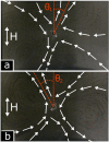
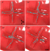
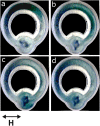
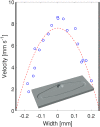
We propose a new class of magnetically actuated pumps and valves that could be incorporated into microfluidic chips with no further external connections. The idea is to repurpose ferromagnetic low Reynolds number swimmers as devices capable of generating fluid flow, by restricting the swimmers' translational degrees of freedom. We experimentally investigate the flow structure generated by a pinned swimmer in different scenarios, such as unrestricted flow around it as well as flow generated in straight, cross-shaped, Y-shaped and circular channels. This demonstrates the feasibility of incorporating the device into a channel and its capability of acting as a pump, valve and flow splitter. Different regimes could be selected by tuning the frequency and amplitude of the external magnetic field driving the swimmer, or by changing the channel orientation with respect to the field. This versatility endows the device with varied functionality which, together with the robust remote control and reproducibility, makes it a promising candidate for several applications.
Conflict of interest statement
The authors declare that they have no competing interests.
Figures


Similar articles
-
Magnetically controlled ferromagnetic swimmers.Sci Rep. 2017 Mar 9;7:44142. doi: 10.1038/srep44142. Sci Rep. 2017. PMID: 28276490 Free PMC article.
-
Magnetically driven omnidirectional artificial microswimmers.Soft Matter. 2018 May 2;14(17):3415-3422. doi: 10.1039/c8sm00230d. Soft Matter. 2018. PMID: 29670984
-
Pressure-actuated monolithic acrylic microfluidic valves and pumps.Lab Chip. 2018 Feb 13;18(4):662-669. doi: 10.1039/c7lc01337j. Lab Chip. 2018. PMID: 29367991
-
Advancements in the research of finger-actuated POCT chips.Mikrochim Acta. 2023 Dec 29;191(1):65. doi: 10.1007/s00604-023-06140-z. Mikrochim Acta. 2023. PMID: 38158397 Review.
-
[Bio-artificial organs: cardiac applications].Verh K Acad Geneeskd Belg. 2004;66(4):246-52. Verh K Acad Geneeskd Belg. 2004. PMID: 15553097 Review. Dutch.
Cited by
-
A Compact Hydraulic Head Auto-Regulating Module (CHARM) for long-term constant gravity-driven flow microfluidics.Microsyst Nanoeng. 2025 May 29;11(1):113. doi: 10.1038/s41378-025-00968-6. Microsyst Nanoeng. 2025. PMID: 40442074 Free PMC article.
-
Direct dynamic read-out of molecular chirality with autonomous enzyme-driven swimmers.Nat Chem. 2021 Dec;13(12):1241-1247. doi: 10.1038/s41557-021-00798-9. Epub 2021 Oct 14. Nat Chem. 2021. PMID: 34650234
-
Electro-actuated valves and self-vented channels enable programmable flow control and monitoring in capillary-driven microfluidics.Sci Adv. 2020 Apr 17;6(16):eaay8305. doi: 10.1126/sciadv.aay8305. eCollection 2020 Apr. Sci Adv. 2020. PMID: 32494605 Free PMC article.
-
Numerical investigation of flexible Purcell-like integrated microfluidic pumps.J Appl Phys. 2022 Oct 28;132(16):164701. doi: 10.1063/5.0109263. Epub 2022 Oct 25. J Appl Phys. 2022. PMID: 36313737 Free PMC article.
-
Microfluidic devices powered by integrated elasto-magnetic pumps.Lab Chip. 2020 Nov 10;20(22):4285-4295. doi: 10.1039/d0lc00935k. Lab Chip. 2020. PMID: 33094306 Free PMC article.
References
-
- Zahn, J. D. Micropump Applications in Bio-MEMS. In. W. Wang, W. & Soper, S. A., Bio-MEMS - Technologies and Applications, CRC Press, vol. 4, 142–176 (2007).
-
- Nikitopoulos, D. E. & Maha, A. Micromixers. In. W. Wang and Soper, S. A. Bio-MEMS - Technologies and Applications, CRC Press, vol. 4, 177–212 (2007).
-
- Au, K, A. Lai, H., Utela, R., B. & Folch, A. A comprehensive study of micropumps technologies. Micromachines2 (2011).
-
- Purcell EM. Life at low Reynolds number. Am. J. Phys. 1977;45:3–11. doi: 10.1119/1.10903. - DOI
-
- Shapere A, Wilczek F. Geometry of self-propulsion at low Reynolds number. J. Fluid Mech. 1989;198:557. doi: 10.1017/S002211208900025X. - DOI
Publication types
LinkOut - more resources
Full Text Sources
Other Literature Sources

