Review
. 2017 Dec 2;51(3 Suppl 1):S102-S121.
doi: 10.17096/jiufd.00289. eCollection 2017.

Cone beam computed tomography: basics and applications in dentistry

Affiliations
Review

Cone beam computed tomography: basics and applications in dentistry

Elluru Venkatesh et al. J Istanb Univ Fac Dent. .

Abstract

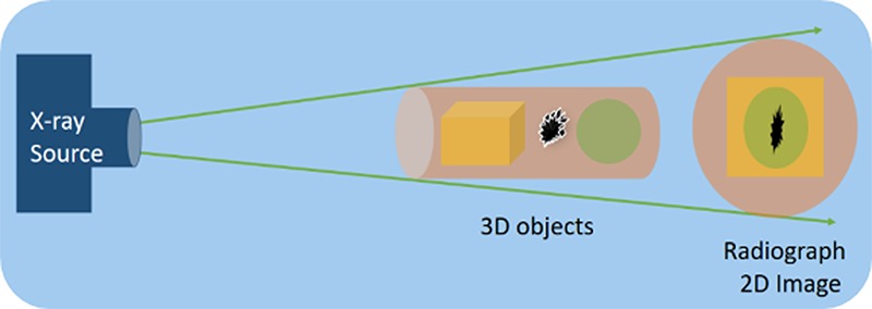
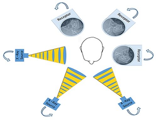
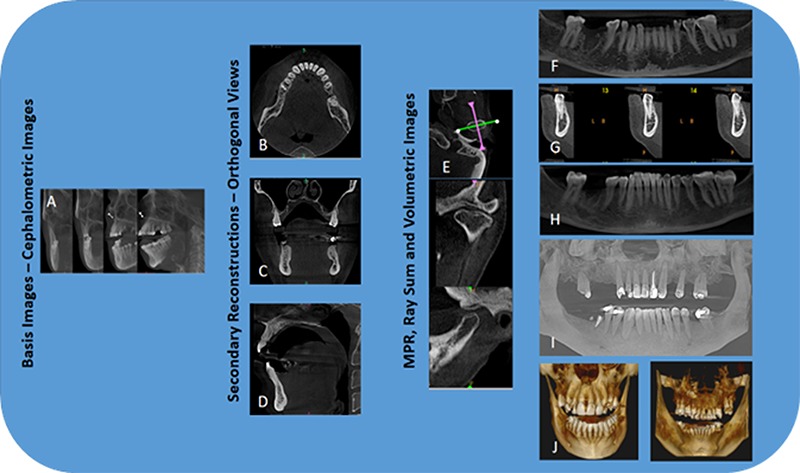
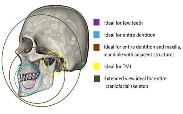
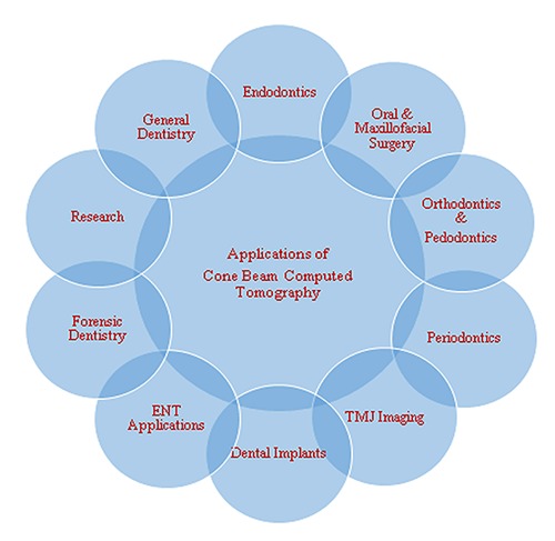
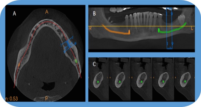
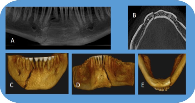
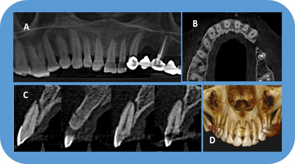
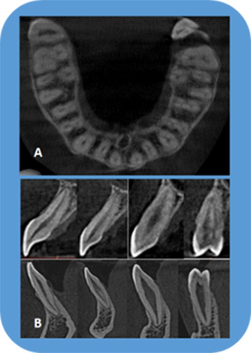
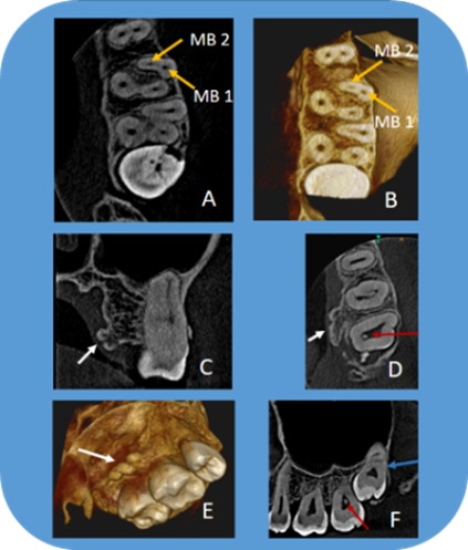
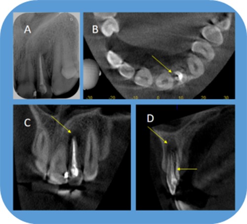
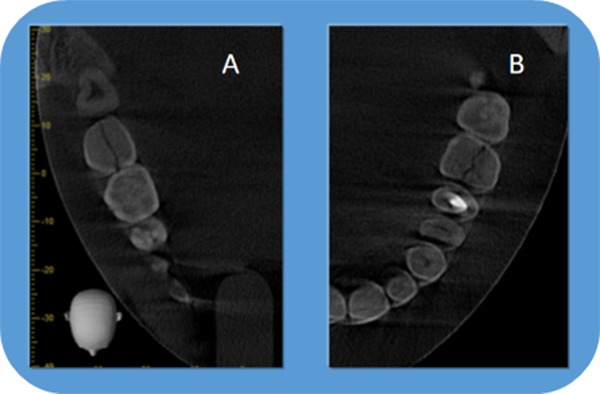
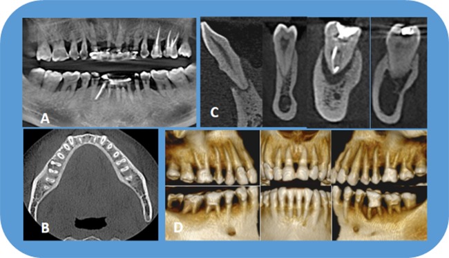
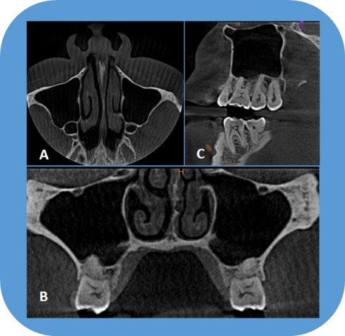
The introduction of cone beam computed tomography (CBCT) devices, changed the way oral and maxillofacial radiology is practiced. CBCT was embraced into the dental settings very rapidly due to its compact size, low cost, low ionizing radiation exposure when compared to medical computed tomography. Alike medical CT, 3 dimensional evaluation of the maxillofacial region with minimal distortion is offered by the CBCT. This article provides an overview of basics of CBCT technology and reviews the specific application of CBCT technology to oral and maxillofacial region with few illustrations.

Keywords: Cone beam computed tomography; dentistry; oral and maxillofacial imaging; radiography; x-ray.


Conflict of interest statement

Conflict of interest: None declared.

Figures

Figure 1.
Figure 1.
2D Imaging, compression of three-dimensional objects into superimposed, distorted two-dimensional images on the resultant radiograph.
Figure 2.
Figure 2.
CBCT, Principle of basis image acquisition where in X-ray source and Image receptor reciprocate around patient 180 – 360 degrees to acquire 180 – 1024, 2D cephalometric images (Basis images).
Figure 3.
Figure 3.
CBCT: Image acquisition and display modes. Acquired 2D Basis images (A) are used for Secondary reconstruction of axial (B), coronal (C) and sagittal (D) views (orthogonal views). Other display modes available in CBCT include (i) multiplanar reformatted (MPR) consisting of Oblique slices (E) Curved slice (F) and Cross sectional views (G); (ii) Ray sum comprising images of increased section thickness (H); and (iii) volumetric images consisting of Direct volume rendering (DVR), the most common of which being maximum intensity projection (MIP) (I) and Indirect volume rendering (IVR) (J).
Figure 4.
Figure 4.
Showing the capability of CBCT machines to collimate (select FOV’s) the X-ray beam to suit the needs of individual clinical situations.
Figure 5.
Figure 5.
Applications of CBCT in various dental specialties.
Figure 6.
Figure 6.
CBCT scan– MPR showing axial view (A) with curved line (red solid line) for “panoramic” view (B) and set of cross-sections, 1-mm-thick images (C) of a potential implant site in the lower left mandible. Blue lines on the axial and panoramic images indicate the location of the cross-sections. Apart from information of bone quality and dimensions, the cross-sections reveal the amount of lingual undercut and location of the inferior alveolar canal (green).
Figure 7.
Figure 7.
Three Dimensional visualization of right parasymphysis fracture of mandible on CBCT scan – Panoramic view (A), Axial view (B) and IVR (C, D, E).
Figure 8.
Figure 8.
MPR is very useful in evaluating dentoalveolar fractures, which are easily missed on 2D imaging. The present CBCT scan reveals dentoalveolar fracture associated with maxillary anterior teeth in different display modes.
Figure 9.
Figure 9.
CBCT scan - Axial image (A) with oblique curved line (Red solid line) and resultant “panoramic” image (B) and set of cross-sections, 1.1 mm thick images (C) of a left anterior region in the maxilla. The cross-sections revealing expansion and perforation of facial and palatal cortical plates due to radicular cyst.
Figure 10.
Figure 10.
CBCT scan - Panoramic view (A), Axial view (B) Cross sections (C) and IVR (D) showing the radiographic features of Stafne bone cavity on the right side of the body of the mandible.
Figure 11.
Figure 11.
CBCT scan- Panoramic view (A), Axial views (B), crossections (C) and IVR reveal radiographic features (sequestration, altered density of trabecular bone, cortical expansion, compression of the mandibular canal) of a case of chronic osteomyelitis.
Figure 12.
Figure 12.
CBCT scan: Axial view (A) showing buccolingual positioning of crown and root of impacted third molar. Panoramic view (B and C) revealing relationship of third molar with mandibular canal and second molar. Set of cross sections (D) revealing the relationship with the mandibular canal.
Figure 13.
Figure 13.
CBCT scan: Panoramic (A), Axial (B) views and (C) crossections reveal iatrogenic injury (accidental sectioning of distal root of second molar, yellow arrow) during third molar removal.
Figure 14.
Figure 14.
CBCT (MPR, Panoramic view) revealing retention cyst in the both the maxillary sinuses.
Figure 15.
Figure 15.
CBCT scans - Extended FOV for Orthodontic and Airway analysis.
Figure 16.
Figure 16.
Orthodontic applications revealing evaluation of impacted canine by CBCT.
Figure 17.
Figure 17.
CBCT images used for assessment of orthodontic treatment involving impacted canines.
Figure 18.
Figure 18.
CBCT showing TMJ; Bilateral oblique MPR through lateral and medial poles of the condyle on the axial image showing coronal (B), sagittal view (C) and IVR (D) with right side showing bifid condyle (yellow arrow).
Figure 19.
Figure 19.
CBCT scans provide a three dimensional evaluation of periapical pathology along with information of the canal morphology. Present scan (a. panoramic view, b. Axial view and C. crossections) shows periapical lesion with right mandibular second premolar.
Figure 20.
Figure 20.
Periapical radiograph (A) shows root canal treated left maxillary second molar with periapical lesion. CBCT scans, axial (B) and coronal (C) view revealing missed distopalatal canal (yellow arrow) with periapical radiolucency and palatal perforation (white arrow) with intact floor of the maxillary sinus in relation to left maxillary second molar.
Figure 21.
Figure 21.
CBCT images (axial and crossections) are indispensable in endodontics for the evaluation of morphology of the tooth including location and number of canals, pulp chamber size and degree of calcification, root structure, direction and curvature, fractures, iatrogenic defects, and the extent of dental caries. The images also allow measurements free from distortion and magnification.
Figure 22.
Figure 22.
Small FOV, CBCT scan of left posterior maxilla showing MB2 canal in first molar (A, B), exostosis (C,D,E), pulp stone in second molar (D,F), third molar relationship with sinus (F), and the sinus devoid of any pathology.
Figure 23.
Figure 23.
Periapical radiograph (A) showing root canal treated maxillary left lateral incisor without any significant changes. In the CBCT, axial (B), coronal (C) and sagittal (D) view showing periapical lesion with vertical root fracture (Yellow arrow).
Figure 24.
Figure 24.
Axial views of two CBCT scans reveal vertical fracture in left lower second molar (A) and left maxillary first molar (B).
Figure 25.
Figure 25.
CBCT scan: Periodontal evaluation – Panoramic view (A) showing horizontal bone loss with furcation involvement. Axial views (B) are useful for evaluating furcation involvements where as crossections are particularly useful in evaluating buccal and lingual cortical plates as well as defining endo/ perio lesions. IVR (D) showing periodontal situation, which can used as tool for educating the patients.
Figure 26.
Figure 26.
ENT applications of CBCT: MPR can be used for evaluation of paranasal air sinuses. Mild deviation of the nasal septum towards left side can be appreciated in the present scan along with other features of maxillary sinus

References

    1. Goldman LW. Principles of CT and CT technology. J Nucl Med Technol. 2007. September;35(3):115–28. 10.2967/jnmt.107.042978 - DOI - PubMed
    1. Arai Y, Tammisalo E, Iwai K, Hashimoto K, Shinoda K. Development of a compact computed tomographic apparatus for dental use. Dentomaxillofac Radiol. 1999. July;28(4):245–8. 10.1038/sj.dmfr.4600448 - DOI - PubMed
    1. Mozzo P, Procacci C, Tacconi A, Martini PT, Andreis IA. A new volumetric CT machine for dental imaging based on the cone-beam technique: preliminary results. Eur Radiol. 1998;8(9):1558–64. 10.1007/s003300050586 - DOI - PubMed
    1. Feldkamp LA, Davis LC, Kress JW. Practical cone-beam algorithm. J Opt Soc Am. 1984;1(6):612–9. 10.1364/JOSAA.1.000612 - DOI
    1. Danforth RA, Miles DA. Cone beam volume imaging (cbvi): 3d applications for dentistry. Irish Dent. 2007;10(9):14–8.

LinkOut - more resources