. 2018 Jan 22;8(1):1293.
doi: 10.1038/s41598-018-19273-6.

Characterization of Carbon-Contaminated B4C-Coated Optics after Chemically Selective Cleaning with Low-Pressure RF Plasma

Affiliations

Characterization of Carbon-Contaminated B4C-Coated Optics after Chemically Selective Cleaning with Low-Pressure RF Plasma

H Moreno Fernández et al. Sci Rep. .

Abstract

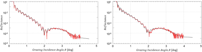
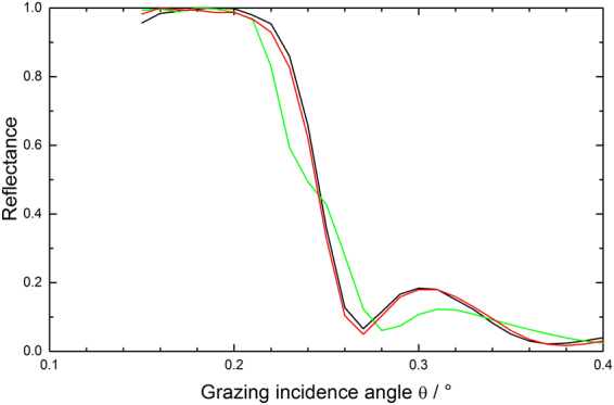
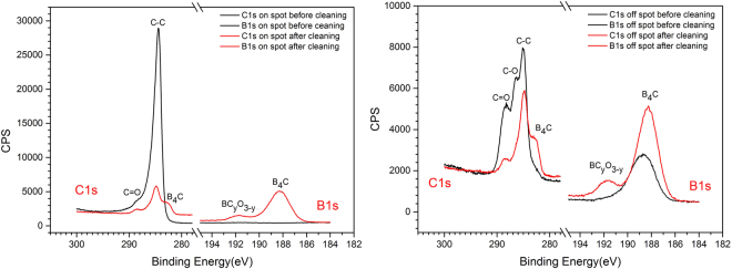
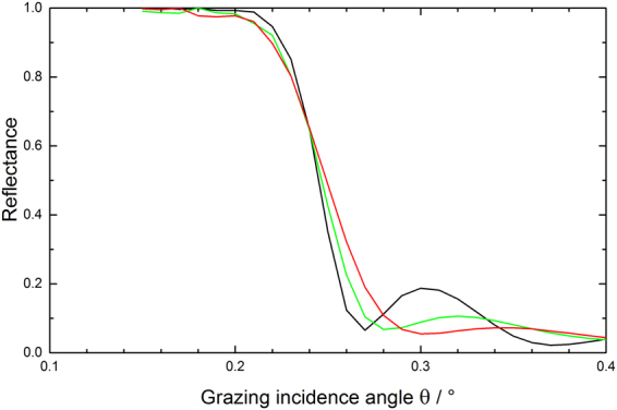
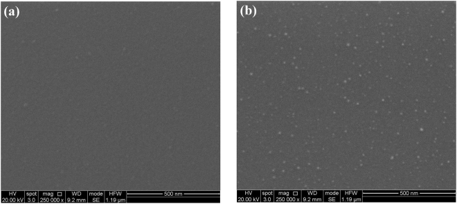
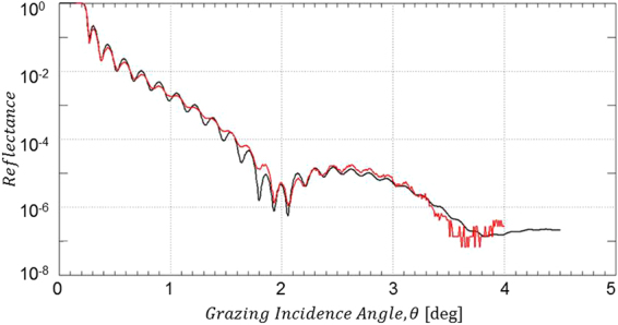
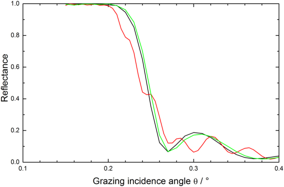
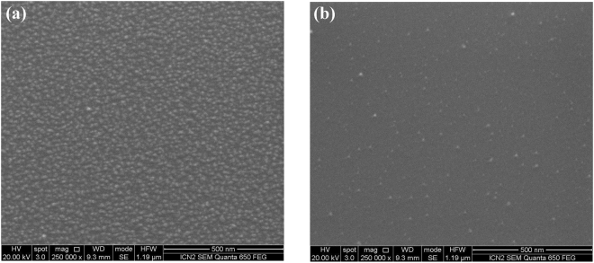
Boron carbide (B4C) is one of the few materials that is expected to be most resilient with respect to the extremely high brilliance of the photon beam generated by free electron lasers (FELs) and is thus of considerable interest for optical applications in this field. However, as in the case of many other optics operated at light source facilities, B4C-coated optics are subject to ubiquitous carbon contaminations. Carbon contaminations represent a serious issue for the operation of FEL beamlines due to severe reduction of photon flux, beam coherence, creation of destructive interference, and scattering losses. A variety of B4C cleaning technologies were developed at different laboratories with varying success. We present a study regarding the low-pressure RF plasma cleaning of carbon contaminated B4C test samples via inductively coupled O2/Ar, H2/Ar, and pure O2 RF plasma produced following previous studies using the same ibss GV10x downstream plasma source. Results regarding the chemistry, morphology as well as other aspects of the B4C optical coating before and after the plasma cleaning are reported. We conclude that among the above plasma processes only plasma based on pure O2 feedstock gas exhibits the required chemical selectivity for maintaining the integrity of the B4C optical coatings.


Conflict of interest statement

The authors declare that they have no competing interests.

Figures

Figure 1
Figure 1
High-resolution C1s and B1s XPS spectra of the B4C-coated test wafer before (black solid lines) and after O2/Ar RF plasma cleaning (red solid lines). Left panel: XPS data taken on the amorphous carbon contamination spot. Right panel: XPS data taken off the amorphous carbon contamination spot on the bare B4C coating.
Figure 2
Figure 2
XRR data from B4C-coated test mirror right after O2/Ar plasma cleaning. Left hand side: Non a-C coated part; right hand side: Formerly a-C coated part (red solid lines: experimental XRR data; black solid lines: IMD simulation).
Figure 3
Figure 3
Comparison of XRR total reflection data at low grazing incidence angles for a pristine B4C-coated test mirror (black line) and after a-C coating plus subsequent O2/Ar plasma cleaning (green line: formerly a-C coated area; red line: non a-C coated area).
Figure 4
Figure 4
SEM images of B4C-coated test wafers taken at 20 kV electron acceleration voltage with a 250 k-fold magnification: (a) Pristine B4C-coated test wafer, (b) O2/Ar-plasma cleaned – formerly a-C coated part, and (c) O2/Ar-plasma cleaned – non a-C coated part.
Figure 5
Figure 5
High-resolution C1s and B1s XPS spectra of the B4C-coated test wafer before (black solid lines) and after H2/Ar RF plasma cleaning (red solid lines). Left panel: XPS data taken on the amorphous carbon contamination spot. Right panel: XPS data taken off the amorphous carbon contamination spot on the bare B4C coating.
Figure 6
Figure 6
XRR data from B4C-coated test mirror right after H2/Ar plasma cleaning. Left hand side: Non a-C coated part; right hand side: Formerly a-C coated part (red solid lines: experimental XRR data; black solid lines: IMD simulation).
Figure 7
Figure 7
Comparison of XRR total reflection data at low grazing incidence angles for a pristine B4C-coated test mirror (black line) and after a-C coating plus subsequent H2/Ar plasma cleaning (green line: formerly a-C coated area; red line: non a-C coated area).
Figure 8
Figure 8
SEM images of B4C-coated test wafers taken at 20 kV electron acceleration voltage with a 250 k-fold magnification after cleaning with H2/Ar plasma: (a) Formerly a-C coated part, and (b) non a-C coated part.
Figure 9
Figure 9
High-resolution C1s and B1s XPS spectra of the B4C-coated test wafer before (black solid lines) and after pure O2 RF plasma cleaning (red solid lines). Left panel: XPS data taken on the amorphous carbon contamination spot. Right panel: XPS data taken off the amorphous carbon contamination spot on the bare B4C coating.
Figure 10
Figure 10
XRR data from B4C-coated test mirror after cleaning with pure O2 plasma cleaning. (red solid lines: experimental XRR data; black solid lines: IMD simulation).
Figure 11
Figure 11
Comparison of XRR total reflection data at low grazing incidence angles for a pristine B4C-coated test mirror (black line), after a-C coating (red line), and after subsequent cleaning with pure O2 plasma (green line).
Figure 12
Figure 12
SEM images of B4C-coated test wafers taken at 20 kV electron acceleration voltage with a 250k-fold magnification after cleaning with pure O2 plasma: (a) Formerly a-C coated part, and (b) non a-C coated part.

References

    1. Domnich V, Reynaud S, Haber RA, Chhowalla M. Boron carbide: Structure, properties, and stability under stress. J. Am. Ceram. Soc. 2011;94:3605–3628. doi: 10.1111/j.1551-2916.2011.04865.x. - DOI
    1. Stoermer M, Siewert F, Sinn H. Preparation and characterization of B4C coatings for advanced research light sources. J. Synchrotron Radiat. 2016;23:50–58. doi: 10.1107/S1600577515020901. - DOI - PMC - PubMed
    1. Mertens, B. et al. EUV time-resolved studies on carbon growth and cleaning. In (ed. Engelstad, R. L.) 95, 10.1117/12.504542 (2003).
    1. Boller K, Haelbich R-P, Hogrefe H, Jark W, Kunz C. Investigation of carbon contamination of mirror surfaces exposed to synchrotron radiation. Nucl. Instruments Methods Phys. Res. 1983;208:273–279. doi: 10.1016/0167-5087(83)91134-1. - DOI
    1. Koide T, et al. Investigation of carbon contamination of synchrotron radiation mirrors. Nucl. Instruments Methods Phys. Res. Sect. A Accel. Spectrometers, Detect. Assoc. Equip. 1986;246:215–218. doi: 10.1016/0168-9002(86)90077-X. - DOI

Publication types

LinkOut - more resources