

Mesh Nanoelectronics: Seamless Integration of Electronics with Tissues
- PMID: 29381054
- PMCID: PMC5820158
- DOI: 10.1021/acs.accounts.7b00547
Mesh Nanoelectronics: Seamless Integration of Electronics with Tissues
Abstract
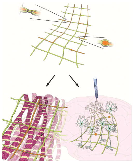
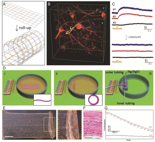
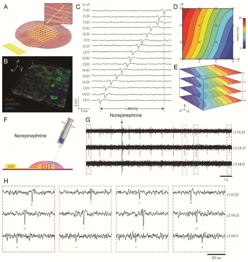
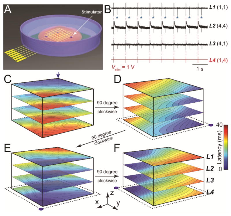
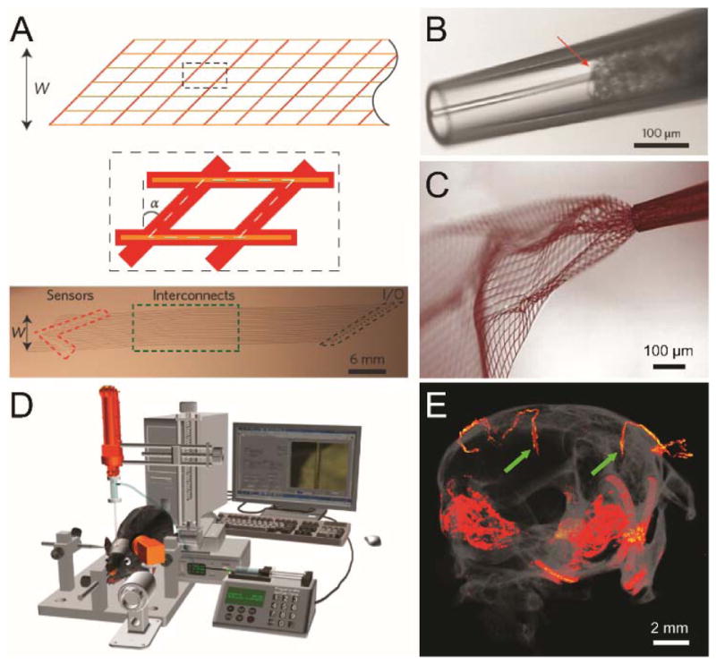
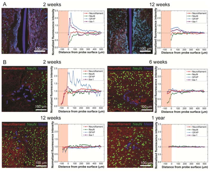
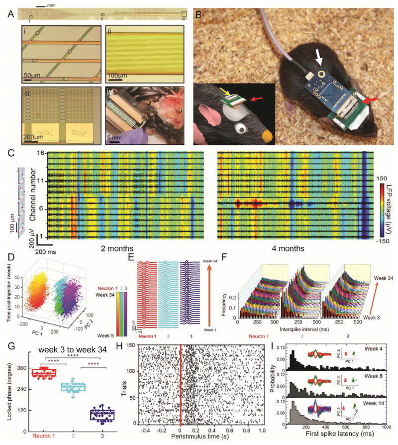
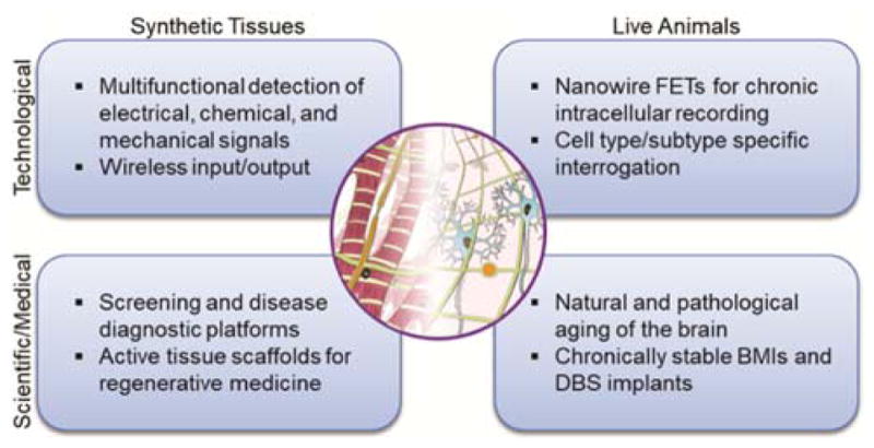
Nanobioelectronics represents a rapidly developing field with broad-ranging opportunities in fundamental biological sciences, biotechnology, and medicine. Despite this potential, seamless integration of electronics has been difficult due to fundamental mismatches, including size and mechanical properties, between the elements of the electronic and living biological systems. In this Account, we discuss the concept, development, key demonstrations, and future opportunities of mesh nanoelectronics as a general paradigm for seamless integration of electronics within synthetic tissues and live animals. We first describe the design and realization of hybrid synthetic tissues that are innervated in three dimensions (3D) with mesh nanoelectronics where the mesh serves as both as a tissue scaffold and as a platform of addressable electronic devices for monitoring and manipulating tissue behavior. Specific examples of tissue/nanoelectronic mesh hybrids highlighted include 3D neural tissue, cardiac patches, and vascular constructs, where the nanoelectronic devices have been used to carry out real-time 3D recording of electrophysiological and chemical signals in the tissues. This novel platform was also exploited for time-dependent 3D spatiotemporal mapping of cardiac tissue action potentials during cell culture and tissue maturation as well as in response to injection of pharmacological agents. The extension to simultaneous real-time monitoring and active control of tissue behavior is further discussed for multifunctional mesh nanoelectronics incorporating both recording and stimulation devices, providing the unique capability of bidirectional interfaces to cardiac tissue. In the case of live animals, new challenges must be addressed, including minimally invasive implantation, absence of deleterious chronic tissue response, and long-term capability for monitoring and modulating tissue activity. We discuss each of these topics in the context of implantation of mesh nanoelectronics into rodent brains. First, we describe the design of ultraflexible mesh nanoelectronics with size features and mechanical properties similar to brain tissue and a novel syringe-injection methodology that allows the mesh nanoelectronics to be precisely delivered to targeted brain regions in a minimally invasive manner. Next, we discuss time-dependent histology studies showing seamless and stable integration of mesh nanoelectronics within brain tissue on at least one year scales without evidence of chronic immune response or glial scarring characteristic of conventional implants. Third, armed with facile input/output interfaces, we describe multiplexed single-unit recordings that demonstrate stable tracking of the same individual neurons and local neural circuits for at least 8 months, long-term monitoring and stimulation of the same groups of neurons, and following changes in individual neuron activity during brain aging. Moving forward, we foresee substantial opportunities for (1) continued development of mesh nanoelectronics through, for example, broadening nanodevice signal detection modalities and taking advantage of tissue-like properties for selective cell targeting and (2) exploiting the unique capabilities of mesh nanoelectronics for tackling critical scientific and medical challenges such as understanding and potentially ameliorating cell and circuit level changes associated with natural and pathological aging, as well as using mesh nanoelectronics as active tissue scaffolds for regenerative medicine and as neuroprosthetics for monitoring and treating neurological diseases.
Conflict of interest statement
The authors declare no competing financial interest.
Figures
Similar articles
-
Nanoelectronics-biology frontier: From nanoscopic probes for action potential recording in live cells to three-dimensional cyborg tissues.Nano Today. 2013 Aug 1;8(4):351-373. doi: 10.1016/j.nantod.2013.05.001. Nano Today. 2013. PMID: 24073014 Free PMC article.
-
Tissue-like Neural Probes for Understanding and Modulating the Brain.Biochemistry. 2018 Jul 10;57(27):3995-4004. doi: 10.1021/acs.biochem.8b00122. Epub 2018 Mar 19. Biochemistry. 2018. PMID: 29529359 Free PMC article.
-
Syringe-injectable Mesh Electronics for Stable Chronic Rodent Electrophysiology.J Vis Exp. 2018 Jul 21;(137):58003. doi: 10.3791/58003. J Vis Exp. 2018. PMID: 30080192 Free PMC article.
-
Mesh electronics: a new paradigm for tissue-like brain probes.Curr Opin Neurobiol. 2018 Jun;50:33-41. doi: 10.1016/j.conb.2017.11.007. Epub 2017 Dec 1. Curr Opin Neurobiol. 2018. PMID: 29202327 Free PMC article. Review.
-
Nanoelectronics meets biology: from new nanoscale devices for live-cell recording to 3D innervated tissues.Chem Asian J. 2013 Oct;8(10):2304-14. doi: 10.1002/asia.201300630. Epub 2013 Aug 15. Chem Asian J. 2013. PMID: 23946279 Free PMC article. Review.
Cited by
-
Nanowire-Enabled Bioelectronics.Nano Today. 2021 Jun;38:101135. doi: 10.1016/j.nantod.2021.101135. Epub 2021 Mar 20. Nano Today. 2021. PMID: 36970717 Free PMC article.
-
Human Brain/Cloud Interface.Front Neurosci. 2019 Mar 29;13:112. doi: 10.3389/fnins.2019.00112. eCollection 2019. Front Neurosci. 2019. PMID: 30983948 Free PMC article.
-
Gels, jets, mosquitoes, and magnets: a review of implantation strategies for soft neural probes.J Neural Eng. 2020 Sep 11;17(4):041002. doi: 10.1088/1741-2552/abacd7. J Neural Eng. 2020. PMID: 32759476 Free PMC article. Review.
-
An Integrated Optogenetic and Bioelectronic Platform for Regulating Cardiomyocyte Function.bioRxiv [Preprint]. 2023 Dec 15:2023.12.15.571704. doi: 10.1101/2023.12.15.571704. bioRxiv. 2023. Update in: Adv Sci (Weinh). 2024 Sep;11(36):e2402236. doi: 10.1002/advs.202402236. PMID: 38168441 Free PMC article. Updated. Preprint.
-
Multifunctional Freestanding Microprobes for Potential Biological Applications.Sensors (Basel). 2019 May 20;19(10):2328. doi: 10.3390/s19102328. Sensors (Basel). 2019. PMID: 31137584 Free PMC article.
References
-
- Lacour SP, Courtine G, Guck J. Materials and technologies for soft implantable neuroprostheses. Nat Rev Mater. 2016;1:16063.
-
- Zhou W, Dai XC, Lieber CM. Advances in nanowire bioelectronics. Rep Prog Phys. 2016;80:016701. - PubMed
-
- Polikov VS, Tresco PA, Reichert WM. Response of brain tissue to chronically implanted neural electrodes. J Neurosci Methods. 2005;148:1–18. - PubMed
Publication types
MeSH terms
Grants and funding
LinkOut - more resources
Full Text Sources
Other Literature Sources
