

Evaluation of the osteogenesis and osseointegration of titanium alloys coated with graphene: an in vivo study
- PMID: 29382859
- PMCID: PMC5790016
- DOI: 10.1038/s41598-018-19742-y
Evaluation of the osteogenesis and osseointegration of titanium alloys coated with graphene: an in vivo study
Abstract
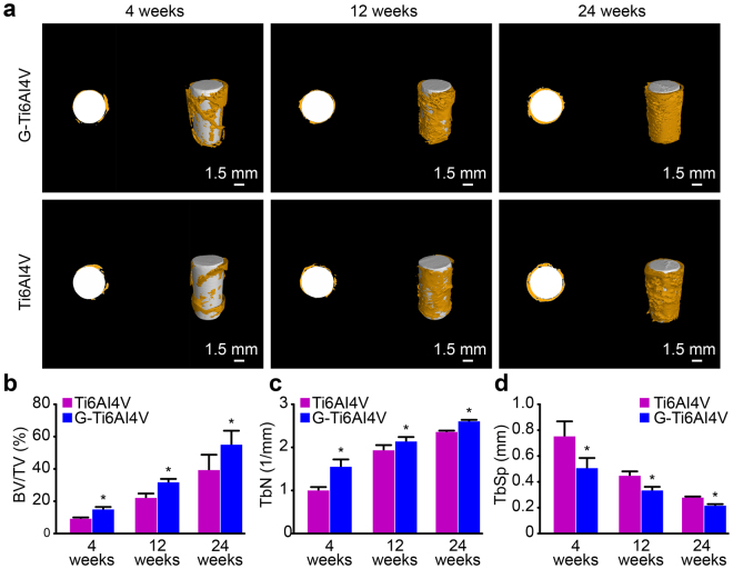
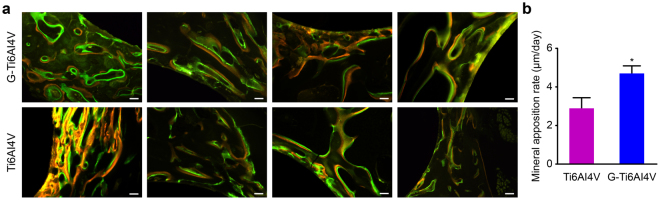
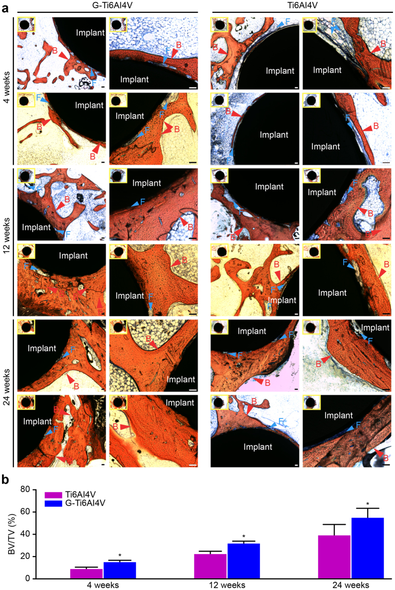
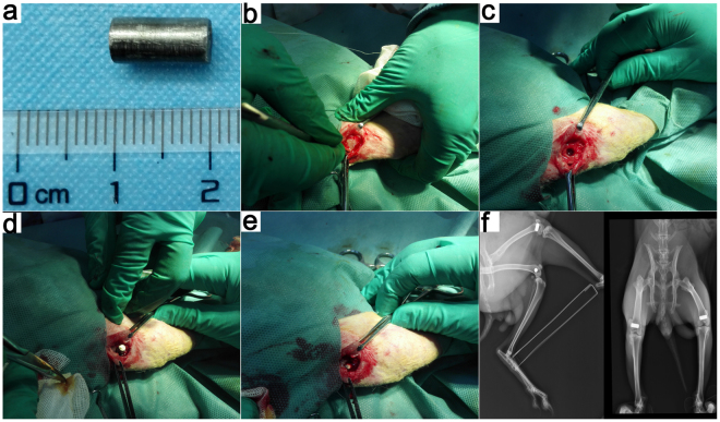
The aim of this study was to investigate whether a surface coating with graphene could enhance the surface bioactivation of titanium alloys (Ti6Al4V) to further accelerate in vivo osteogenesis and osseointegration at the implant surface. In this study, a New Zealand white rabbit femoral condyle defect model was established. After 4, 12 and 24 weeks, biomechanical testing, micro-computed tomography (Micro-CT) analyses and histological observations were performed. At the highest push-out forces during the test, microstructure parameters, such as the bone volume/total volume fraction (BV/TV) and mineral apposition rate (MAR), of the new bone were significantly higher in the graphene-coated Ti6Al4V group (G-Ti6Al4V) than in the Ti6Al4V group (P < 0.05). Van Gieson (VG) staining showed that the G-Ti6Al4V group had more new bone formation than the Ti6Al4V group, and the G-Ti6Al4V group showed a closer fit between the bone and implant. In conclusion, graphene might be a novel type of nano-coating material for enhancing the surface biological activity of Ti-based alloy materials and may further promote in vivo osteogenesis and osseointegration.
Conflict of interest statement
The authors declare that they have no competing interests.
Figures


Similar articles
-
Enhanced Osseointegration of Titanium Alloy Implants with Laser Microgrooved Surfaces and Graphene Oxide Coating.ACS Appl Mater Interfaces. 2019 Oct 30;11(43):39470-39483. doi: 10.1021/acsami.9b12733. Epub 2019 Oct 17. ACS Appl Mater Interfaces. 2019. PMID: 31594306
-
Safety and efficacy of additive and subtractive surface modification of Ti6Al4V endosseous implant in goat bone.J Mech Behav Biomed Mater. 2016 Apr;57:69-87. doi: 10.1016/j.jmbbm.2015.11.019. Epub 2015 Dec 4. J Mech Behav Biomed Mater. 2016. PMID: 26705934
-
Study on the Antibacterial Activity and Bone Inductivity of Nanosilver/PLGA-Coated TI-CU Implants.Int J Nanomedicine. 2024 Jun 24;19:6427-6447. doi: 10.2147/IJN.S456906. eCollection 2024. Int J Nanomedicine. 2024. PMID: 38952675 Free PMC article.
-
A systematic review of preclinical in vivo testing of 3D printed porous Ti6Al4V for orthopedic applications, part I: Animal models and bone ingrowth outcome measures.J Biomed Mater Res B Appl Biomater. 2021 Oct;109(10):1436-1454. doi: 10.1002/jbm.b.34803. Epub 2021 Jan 22. J Biomed Mater Res B Appl Biomater. 2021. PMID: 33484102
-
The Effect of Antibacterial-Osteogenic Surface Modification on the Osseointegration of Titanium Implants: A Static and Dynamic Strategy.ACS Biomater Sci Eng. 2024 Jul 8;10(7):4093-4113. doi: 10.1021/acsbiomaterials.3c01756. Epub 2024 Jun 3. ACS Biomater Sci Eng. 2024. PMID: 38829538 Review.
Cited by
-
Implant-bone-interface: Reviewing the impact of titanium surface modifications on osteogenic processes in vitro and in vivo.Bioeng Transl Med. 2021 Jul 12;7(1):e10239. doi: 10.1002/btm2.10239. eCollection 2022 Jan. Bioeng Transl Med. 2021. PMID: 35079626 Free PMC article. Review.
-
Direct comparison of additively manufactured porous titanium and tantalum implants towards in vivo osseointegration.Addit Manuf. 2019 Aug;28:259-266. doi: 10.1016/j.addma.2019.04.025. Epub 2019 May 1. Addit Manuf. 2019. PMID: 31406683 Free PMC article.
-
Revolutionizing Dentistry: Preclinical Insights and Future Applications of mRNA Vaccines in Dentistry-A Narrative Review.Dent J (Basel). 2025 Feb 13;13(2):79. doi: 10.3390/dj13020079. Dent J (Basel). 2025. PMID: 39996953 Free PMC article. Review.
-
Synthetic materials in craniofacial regenerative medicine: A comprehensive overview.Front Bioeng Biotechnol. 2022 Nov 9;10:987195. doi: 10.3389/fbioe.2022.987195. eCollection 2022. Front Bioeng Biotechnol. 2022. PMID: 36440445 Free PMC article. Review.
-
Effects of hydroxyapatite-coated porous titanium scaffolds functionalized by exosomes on the regeneration and repair of irregular bone.Front Bioeng Biotechnol. 2023 Oct 31;11:1283811. doi: 10.3389/fbioe.2023.1283811. eCollection 2023. Front Bioeng Biotechnol. 2023. PMID: 38026868 Free PMC article.
References
Publication types
MeSH terms
Substances
LinkOut - more resources
Full Text Sources
Other Literature Sources
