. 2018 Sep;80(3):1233-1242.
doi: 10.1002/mrm.27095. Epub 2018 Feb 1.

Transverse slot antennas for high field MRI

Affiliations

Transverse slot antennas for high field MRI

Leeor Alon et al. Magn Reson Med. 2018 Sep.

Abstract

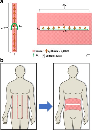
Purpose: Introduce a novel coil design using an electrically long transversely oriented slot in a conductive sheet.

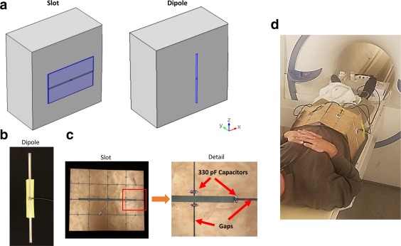
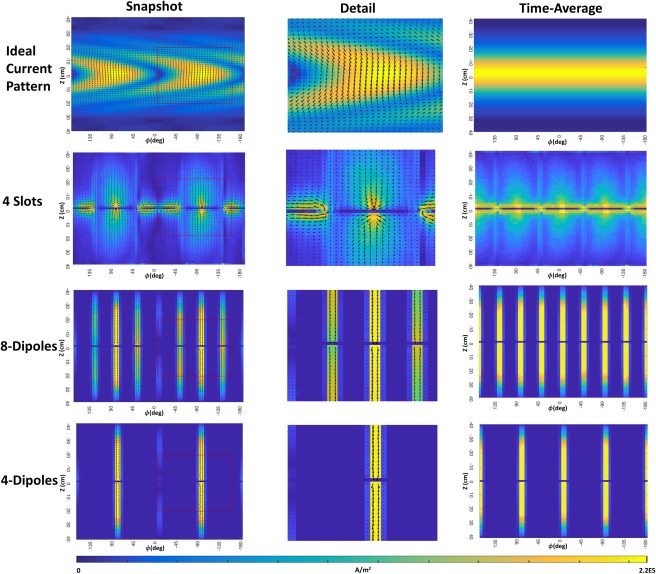
Theory and Methods: Theoretical considerations, numerical simulations, and experimental measurements are presented for transverse slot antennas as compared with electric dipole antennas.

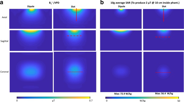
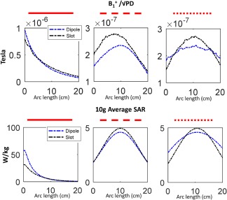
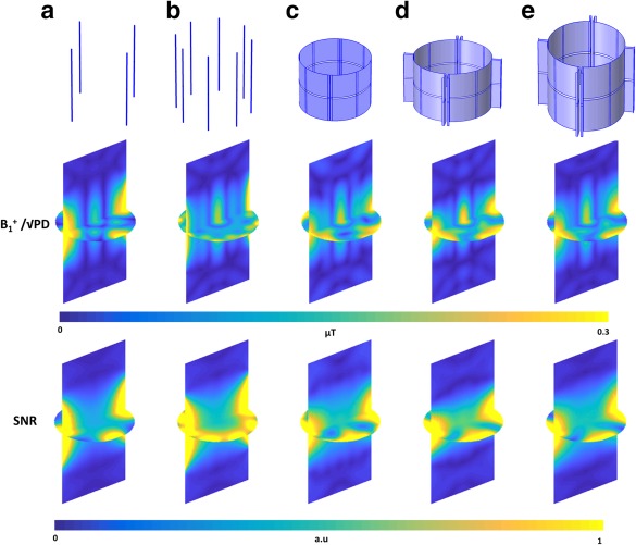
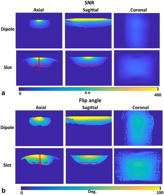
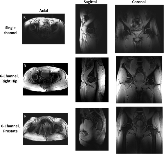
Results: Simulations show improved central and average transmit and receive efficiency, as well as larger coverage in the transverse plane, for a single slot as compared to a single dipole element. Experiments on a body phantom confirm the simulation results for a slot antenna relative to a dipole, demonstrating a large region of relatively high sensitivity and homogeneity. Images in a human subject also show a large imaging volume for a single slot and six slot antenna array. High central transmit efficiency was observed for slot arrays relative to dipole arrays.

Conclusion: Transverse slots can exhibit improved sensitivity and larger field of view compared with traditional conductive dipoles. Simulations and experiments indicate high potential for slot antennas in high field MRI. Magn Reson Med 80:1233–1242, 2018. © 2018 The Authors Magnetic Resonance in Medicine published by Wiley Periodicals, Inc. on behalf of International Society for Magnetic Resonance in Medicine. This is an open access article under the terms of the Creative Commons Attribution NonCommercial License, which permits use, distribution and reproduction in any medium, provided the original work is properly cited and is not used for commercial purposes.

Keywords: RF antennas; coil arrays; high field MRI; slot antenna.


Figures

Figure 1
Figure 1
A: Slotted design (right) produces magnetic fields (green arrows) oriented parallel to the slot, while dipoles produce magnetic fields perpendicular to the conductor (left). B: Considering this field orientation, rotation of the slot relative to conventional dipole antenna designs is appropriate for imaging.
Figure 2
Figure 2
A: Simulation setup of the slot and dipole antenna structures next to a dielectric phantom. Experimental single dipole design (B), slot antenna design (C), and six‐slot array mounted on a subject (D). Narrow gaps with capacitors for blocking low‐frequency gradient‐induced eddy currents are shown in detailed view.
Figure 3
Figure 3
Normalized B1+ maps (A) and 10g average SAR maps (B) for axial and sagittal slices at the center of the antenna, and a coronal slice 10 cm inside the phantom.
Figure 4
Figure 4
1D projections of the normalized B1+ maps and 10g average SAR maps (denoted in red lines in Figure 3) for the slot (black) and dipole (blue) antennas.
Figure 5
Figure 5
B1+ normalized by the square root of PD and SNR computed in the phantom for a four‐element dipole array (A), eight‐element dipole array (B), four‐element encircling slot array (C), four‐element folded slot array (D), and long four‐element folded slot array (E).
Figure 6
Figure 6
Experimental SNR (A) and flip angle (B) maps in axial, sagittal, and coronal planes for a dipole and slot antennas, placed on top of a body phantom.
Figure 7
Figure 7
Imaging results on the hip region of a volunteer using a single experimental slot antenna (top row), and array of six slots with phase‐only shim on right hip (middle row) and prostate (bottom row). Axial, sagittal, and coronal slices acquired using a 2D spoiled GRE sequence are shown.
Figure 8
Figure 8
Ideal current patterns (snapshot and time average) around a cylindrical sample (top row), Currents on the conductive surface for a four‐element slot array (2nd row), eight‐element dipole array (3rd row), and four‐element dipole array (bottom row).

Similar articles

Cited by

References

    1. Vaughan JT, Snyder CJ, DelaBarre LJ, Bolar PJ, Tian J, Bolinger L, Adriany G, Andersen P, Strupp J, Ugurbil K. 7 T whole body imaging: preliminary results. Magn Reson Med 2009;61:244–248. - PMC - PubMed
    1. Vaughan JT, Garwood M, Collins CM, et al. 7T vs. 4T: RF power, homogeneity, and signal‐to‐noise comparison in head images. Magn Reson Med 2001;46:24–30. - PubMed
    1. Hassan A, Elabyed I. Optimal geometry and capacitors distribution of 7T MRI surface coils. In Proceedings of the 40th European Microwave Conference, 2010. pp. 1437–1440.
    1. Brown R, Storey P, Geppert C, McGorty K, Klautau Leite AP, Babb J, Sodickson DK, Wiggins GC, Moy L. Breast MRI at 7 Tesla with a bilateral coil and robust fat suppression. J Magn Reson Imaging 2014;39:540–549. - PMC - PubMed
    1. Vossen M, Teeuwisse W, Reijnierse M, Collins CM, Smith NB, Webb AG. A radiofrequency coil configuration for imaging the human vertebral column at 7 T. J Magn Reson 2011;208:291–297. - PMC - PubMed

Publication types