Review
. 2018 May;30(19):e1704847.
doi: 10.1002/adma.201704847. Epub 2018 Feb 12.

Engineered Living Materials: Prospects and Challenges for Using Biological Systems to Direct the Assembly of Smart Materials

Affiliations
Review

Engineered Living Materials: Prospects and Challenges for Using Biological Systems to Direct the Assembly of Smart Materials

Peter Q Nguyen et al. Adv Mater. 2018 May.

Abstract

Vast potential exists for the development of novel, engineered platforms that manipulate biology for the production of programmed advanced materials. Such systems would possess the autonomous, adaptive, and self-healing characteristics of living organisms, but would be engineered with the goal of assembling bulk materials with designer physicochemical or mechanical properties, across multiple length scales. Early efforts toward such engineered living materials (ELMs) are reviewed here, with an emphasis on engineered bacterial systems, living composite materials which integrate inorganic components, successful examples of large-scale implementation, and production methods. In addition, a conceptual exploration of the fundamental criteria of ELM technology and its future challenges is presented. Cradled within the rich intersection of synthetic biology and self-assembling materials, the development of ELM technologies allows the power of biology to be leveraged to grow complex structures and objects using a palette of bio-nanomaterials.

Keywords: biomaterials; engineered living materials; self-healing; smart materials; synthetic biology.


Figures

Figure 1.
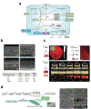
Figure 1.. Properties of Engineered Living Materials.
ELMs leverage the adaptive responses, self-replicating potential, and robustness of biological systems for the programmed assembly and modulation of novel materials. The material can be engineered by genetic, spatial patterning, or chemical means, and can be designed for a wide variety of functions. These ELMs could be employed as micro to large-scale structural materials, as a kind of biohybrid device that integrates synthetic materials with living systems, or for specialty applications such as biocatalysis or toxin sequestration.
Figure 2.
Figure 2.. ELMs as Bioinspired Materials Engineering.
A single seed contains all the essential information needed to create a tree, and it does so by genetically encoding the metabolic functions required for acquiring energy (photosynthesis) and mechanisms for utilizing local resources (carbon dioxide and water). It also contains the information necessary for successful multi-scale hierarchical morphogensis based on principles of cellular self-organization and molecular self-assembly. These living structures are capable of dynamically responding to the environment and can maintain and renew themselves over time. Synthetic ELMs attempt to replicate these characteristics, by using synthetic biology to engineer cells to fabricate, assemble, and maintain autonomously produced materials composed of one or more biomaterials from a library of potential biomaterials. The cells could be metabolically engineered to utilize local energy sources and materials. By also incorporating programmed synthetic morphogenesis, large-scale structures can be designed with complex organization over multiple length scales.
Figure 3.
Figure 3.. Engineering Bacterial Polysaccharides.
(a) Strategy for in vivo generation of modified polysaccharides by metabolic pathway engineering. (b) Generation of polysaccharides containing fucose analogs and their modifications located at C-6 position of fucose. Both images are from Yi, et al.[18]
Figure 4.
Figure 4.. Engineered Polysaccharide-Based ECMs for Functional Biofilms.
(a) Bacterial polymer biosynthesis pathways from intermediates of central metabolism (polysaccharides shown in green).[173] Cellulose (b-d). (b) Engineering the thickness and piezoelectricity of bacterial cellulose.[26] (c) Engineering of spatial and temporal patterned and functionalized cellulose materials on a macroscale.[25] (d) In vivo curdlan and cellulose bionanocomposite synthesis to modulate cellulose properties.[28]
Figure 5.
Figure 5.. Engineered Protein-Based ECMs for Functional Biofilms.
S-layer proteins (a-b). (a) Schematic of S-layer proteins in gram positive and negative bacteria.[30] (b) Scheme of S-layer protein on bacterial cell surface and SEM image of cell surface of Thermoanaerobacter thermohydrosulfuricus L111 showing a hexagonal (p6) surface lattice.[30] (c) The construction of the three paradigmatic systems involved the division of the production and organization of the enzymes and scaffold proteins into different strains of L. plantarum.[35] (d) Scheme of genetic programming and modularity of the BIND system.[39] (e) Catalytic-BIND: biofilm functionalization with enzymes through the covalent modification of curli fibers.[40] (f) SEM/EDS and TEM images of environmentally switchable conductive biofilms.[42] (g) Conceptual depiction of self-regulating mercury binding circuit.[45]
Figure 6.
Figure 6.. Engineering Bacteria to Control Biofilm Pattern Formation.
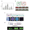
(a) Effect of indole (500 μM) on the biofilm formation and motility of wild-type and engineered E. coli.[48] (b) μBE metabolic circuit with the two E. coli cell types communicate by using the LasI / LasR QS module of P. aeruginosa (top) and dispersal of dual-species biofilms using arabinose (bottom).[47] (c) Toluene degradation pathway from P. putida F1 and partial pathways carried out by mutant strains PpF4 and PpF10732 (top). Spatial patterns arising from the consortium of mutants (bottom).[52] (d) Schematic representation of the engineered plasmid conferring constitutive metal uptake and inducible adhesion (top). Thickness of biofilm formed by the S61 strain in the presence or absence of cobalt and nickel (bottom).[53]
Figure 7.
Figure 7.. Living soft robots’ motion relies on the patterning of cardiac muscle cells.
(a) Muscular thin films exploit the anisotropy of cardiomyocytes seeded onto different fibronectin-patterned PDMS surfaces to generate complex actuation patterns. Left: A strip with anisotropically organized cadiomyocytes coils and uncoils, middle: A rectangular strip with discrete arrayed muscle fibers spontaneously adopts an helical conformation, right: Cardiomyocytes aligned length-wise along a strip form a “gripper” device.[70] (b) The locomotion of a jellyfish was replicated using electrically-stimulated muscle sheets to form a medusoid. [71] (c) An artifical ray robot was fabricated with genetically engineered cardiomyocytes that can respond to optical stimuli. Different frequencies were used for stimulating muscle contraction and for maneuvering.[72]
Figure 8.
Figure 8.
Living cells have been integrated with polymers to create smart functional living polymeric composites with added functionalities. Penicillin-producing fungi cells were used to create (a) living antibiotic-releasing surfaces that can sustain release over time because of their in situ production[62] and (b) smart self-cleaning surfaces that can metabolize food spills.[63]
Figure 9.
Figure 9.. Microorganisms for the production of or the directed assembly of organic polymers.
(a) Several key genes and operons are involved in the synthesis of biopolymers produced by bacteria.[173] (b) Bacterial synthesis of polyhydroxyalkanoates through fermentation is part of the carbon life cycle of these biodegradable polymers.[75] (c) Through their redox metabolism, bacteria can induce polymerization in monomer-catalyst suspensions, resulting in surface-bound polymers.[82]
Figure 10.
Figure 10.. Living composites with carbon materials.
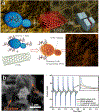
Integrating ELMs with inroganic materials serve for the fabrication of various devices. (a) Bionic composites made of yeast cells fermented with graphene nanoplatelets (GNPs) (top) or carbon nanotubes (CNTs) (bottom).[85, 86] (b) Biomemory device fabricated through the self-assembly of Shewanella oneidensis bacteria with graphene oxide (left: SEM image of the composite, right: Write/erase function of the biomemory device).[87]
Figure 11.
Figure 11.. Silica-based ELMs from Diatom Engineering.
(a) Scanning electron microscopy images of cell walls from different diatom species. Images in top and middle rows show overviews of single silica cell walls, and images in bottom row show details of diatom silica cell walls.[174] (b) Images obtained by confocal fluorescence microscopy of T. pseudonana transformants expressing silaffin fusion protein tpSil3-GFP. The four images in the left half (“cell”) were taken from live cells, the images in the right half (“cell wall”) were taken from isolated biosilica. Each micrograph is an overlay of two images recorded in the “green channel” (excitation: 488 nm, emission: 505/550 nm bandpass filter) and the “red channel” (excitation: 543 nm, emission: 585 nm long‐pass filter). The green color is indicative of GFP, the red color is caused by chloroplast autofluorescence. Scale bar: 2 μm (identical scale for all micrographs).[99] (c) HabB activity in T. pseudonana biosilica. The activity was monitored by following the formation of 2-aminophenol from hydroxylaminobenzene.[99] Line graph: Kinetics of 2-aminophenol formation by identical amounts of biosilica (1.2 mg) isolated from wild-type cells (WT, gray diamonds) and transformants C1 (squares), C2 (filled circles) and C3 (triangles).  Bar graph: Half-life of soluble HabB (white bars), immobilized in biosilica of transformant C1 (black bars), and immobilized in silica produced by the R5 peptide in vitro (gray bars). The HabB-containing samples were subjected to various treatments as indicated.[99] (d) Hypothetical pathway for intracellular transport of silaffin-enzyme fusion proteins to the silica deposition vesicle (SDV). The fusion proteins are cotranslationally imported into the endoplasmic reticulum (ER), and the signal peptide (SP) for ER import is removed by signal peptidase. Further modifications of the fusion proteins may occur in the ER and after transport to and through the Golgi apparatus. The fusion proteins may reach the SDV via specific transport vesicles, and become incorporated into the silica-forming organic matrix in the SDV lumen. After completion of silica formation, the silaffin-enzyme fusion proteins become trapped in the deposited silica and, after exocytosis of the SDV contents, remain stably attached to the biosilica cell wall.[100] (e) Genetically engineered diatom biosilica (green) containing liposome-encapsulated drug molecules (yellow) can be targeted to both adherent neuroblastoma cells (red) and lymphocyte cells in suspension (purple) by functionalizing the biosilica surface with cell-specific antibodies. Liposome-encapsulated drug molecules are released from the biosilica carrier in the immediate vicinity of the target cells (inset).[101]
Figure 12.
Figure 12.. Self-healing Biological Concrete.
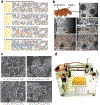
(a) Schematic of crack-healing by concrete-immobilized bacteria. Bacteria on fresh crack surfaces become activated due to water ingression, start to multiply and precipitate minerals such as calcite (CaCO3), which eventually seal the crack[103] (b) Self-healing admixture composed of expanded clay particles (left) loaded with bacterial spores and organic bio-mineral precursor compound (calcium lactate). When embedded in the concrete matrix (right) the clay particles serve as internal reservoirs containing the two-component healing agent consisting of bacterial spores and a suitable bio-mineral precursor compound.[102] Light microscopic images (40x magnification) of pre-cracked control (A) and bacterial (B) concrete specimen before (left) and after (right) healing following 2 weeks of submersion in water. Mineral precipitation occurred predominantly near the crack rim in control but inside the crack in bacterial specimens.[102] (c) Scanning electron micrographs of CaCO3 precipitation in the silica gel and PU foam.[105] (d) bioMASON machine for producing biobricks.[175]
Figure 13.
Figure 13.. Engineered ELMs from Mutualistic Microbial Consortia.
A collection of microorganisms with mutualistic or complementary functions can be assembled to produce functional materials. (a) Living soft matter was produced in situ by growing cellulose-producing bacteria and photosynthetic microalgae.[110] (b) The resulting material consists of a moldable gel of entrapped microalgae in a cellulose matrix.
Figure 14.
Figure 14.. Lignocellulosic Living Organisms as ELMs.
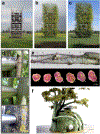
(a-c) Tree shaping allows for the mechanical manipulation of living tree tissues into a growing structure. (d) One version of this architectural design system is known as Baubontanik and incorporates modern design materials with tree shaping, as shown in the construction of a tower. Over time, the trees are able to fuse around temporary metal scaffolding. (e) Tree shaping takes advantage of inosculation, or proximity grafting, the ability of tree tissues in trunks, branches, or roots to fuse together when in close proximity. Shown are cross-sections of inosculated branches. All photos for (a-e) copyright Ferdinand Ludwig. (f) Concept designs of a tree-based habitat in which the tree is shaped using CNC scaffolds. Photo copyright Mitchell Joachim.
Figure 15.
Figure 15.. Mycelium-based ELM materials.
(a) A ‘mycotecture’ concept structure composed of mycelium, Mycotectural Alpha, on exhibit at Kunsthalle Düsseldorf in 2009. Photograph copyright Philip Ross. (b) Mycelium-based bricks for construction. (c) When the bricks are placed together, the mycelium grow into each other, organically fusing the bricks together. (d) The mycelial material can also be shaped into functional structures such as furniture. (e) In addition, flexible materials such as tough leather-like fabrics can be made from mycelium. (f) A photograph of Mycoworks mycelium material shows the wood chip feedstock and the growing mycelial hyphae. Photos (a-f) are all copyright MycoWorks. (g) A flowchart of the process for preparation of mycelial materials. Mycelium-based foam technology from Ecovative Design used for ecologically-friendly packaging (h) and building insulation (i). (j) SEM image of the mycelium from the Ecovative materials. Photos (h-j) copyright Ecovative Design.
Figure 16.
Figure 16.. Large-scale production of bacterial cellulose materials.
(a) Harvested bacterial cellulose material. Photo copyright Scobytec. (b) Skin dressing made from microbial cellulose materials. Photo copyright www.fzmb.de. (c) As a structural material, modular geometric objects can be created from molded bacterial cellulose. Photo copyright Jannis Hülsen. (d) An example of architectural materials made of bacterial cellulose grown on a support scaffold of jute wires. Photo copyright Institute for Advanced Architecture of Catalonia. (e) Bacterial cellulose can also be used as a large-scale textile material, here used to create various garments. Photo copyright Suzanne Lee.
Figure 17.
Figure 17.. Large-scale Bioproduction Technologies for ELMs.
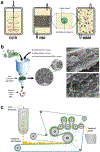
(a) Basic bioreactor architectures. In contrast to CSTR reactors, which are efficient for production of planktonic cells, PBR and MBBRs contain packing materials that allow for the growth of interfacial biomass and are more suited for maximizing biofilm growth. (b) Preparatory-scale ELMs can be separated from the cellular components after growth, using chemical treatments and vacuum-assisted filtration. Right images are SEM micrographs showing isolated layered ELM amyloid mat materials. (c) On an industrial level, high-throughput separation of solids from liquids can be applied to ELMs grown in liquid bioreactors using belt press filters, which sandwiches the material to be processed between two membranes of defined pore size and uses pressure from rollers to remove liquids, producing solids that can be processed further.
Figure 18.
Figure 18.. Electrospun living polymer fibers.
(a) Yeast cells were embedded in a water-soluble polyvinylpyrrolidone (PVP) core matrix, and enveloped with a poly vinylidene fluoride-cohexafluoropropylene shell. In the middle panel, encapsulated yeast cells are shown in purple.[146] (b) Electrospun living bacteria composite fibers were prepared using a poly-(vinyl alcohol) (PVA) core subsequently coated with a hydrophobic poly(p-xylylene) (PPX) shell via chemical vapor deposition (left). The fibers were mounted onto a wire frame (5 cm wide) that could be used for decontamination (right).[147]
Figure 19.
Figure 19.. 3D Printing for Spatial Patterning of ELMs.
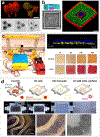
(a) Top: Confocal laser scanning microscopy (CLSM) reconstruction of bacteria (green) within spheroid “rooms” created from photocrosslinked gelatin that are connected by channels (red). Scale bar, 20 μm. Bottom: Light microscopy top view of encapsulated P. aeruginosa cells growing within the microfabricated structure over time. Scale bar, 20 μm. (b) This method can be used to construct complex structures containing different bacterial species, as demonstrated from nested structures where the inner chamber contains S. aureus bacteria surrounded by P. aeruginosa bacteria in the outer chamber. Left: Model and light microscopy image of nested rooms. Right, top: CLSM reconstruction cross-section view of the structure. Scale bars, 10 μm. All images in (a-b) from the Shear group.[149](c) Left: An inexpensive bacterial 3D printer using a modified commercial kit integrated with a syringe pump and alginate-based bioinks. Right: Top shows a CLSM reconstruction of two E. coli populations expressing different fluorescent proteins in different 3D-printed alginate layers. Bottom shows rhamnose-induced expression of RFP from 3D-printed structures, demonstrating viability.[150] (d) Top: schematic and photographs of the 3D tissue-printing process using fugitive ink from the Lewis lab, here used to fabricate a structure simulating kidney nephron tubules[151]. Bottom: After seeding with proximal tubule epithelial cells, shear stress from flow through the printed tubule induces the formation of ECM and functionalization of the cells, forming a polarized tissues that structurally and functionally recapitulate aspects of kidney epithelium. (left to right) Phase contrast images of cells in 3D-printed tubule after 6 weeks, scale bars at 500 and 250 μm. TEM cross-section after 5 weeks, scale bar is 5 μm.
Figure 20.
Figure 20.. Synthetic Morphogenesis for Engineering Hierarchically Defined Multicellular Structures.
(a) Use of AHL production and sensing elements to generate a band detector circuit for genetically programmed morphogenesis. Right, top image shows a bullseye pattern formed by the sender cells in the middle expressing CFP surrounded by two cell types with different band detectors, expressing GFP and DsRed. Right, bottom image shows designed shapes can be generated by defined placement of the sender cells (here expressing DsRed); the GFP cells containing the band detector circuit only grow at a defined AHL range and thus form a heart shape.[161] (b) By combining a genetic dark sensor with an AHL-gradient response circuit, only cells directly adjacent to the dark zones (edges) are turned on by the synthetic circuit, creating an edge-detection device. Bottom images: left shows the photomask used in the experiment, center is a photo of a bacterial lawn containing the edge detector circuit, and right shows the mathematically modeled prediction.[162] (c) Generation of striped patterns from growing populations of bacterial cells using an AHL-generation circuit that stops cellular motility at high cell densities. As cells swarm outward, they produce concentric bands containing nonmotile cells. The stripe periodicity can be tuned genetically.[163] (d) Differential adhesion-based engineering of multicellular patterning, using two populations of mammalian cells expressing two different pairs of cadherins with GFP or mCherry as markers. Epifluorescence microscopy images (left, center) showing the boundary zones. Right, zoom-in confocal fluourescence image. All scale bars are 200 microns.[165] (e) Confocal microscopy image of B. subtilis biofilm populations expressing different fluorescent proteins that self-organize into fractal patterns. Image from University of Cambridge, Fractal Bacteria: Predictably Beautiful 3, by Fernan Federici, PJ Steiner, Tim Rudge, and Jim Haseloff.

References

    1. Chen X, Mahadevan L, Driks A, Sahin O, Nat. Nanotechnol. 2014, 9, 137. - PubMed
    1. Benam KH, Villenave R, Lucchesi C, Varone A, Hubeau C, Lee H-H, Alves SE, Salmon M, Ferrante TC, Weaver JC, Bahinski A, Hamilton GA, Ingber DE, Nat. Methods 2015, 13, 151. - PubMed
    1. Herland A, van der Meer AD, FitzGerald EA, Park T-E, Sleeboom JJF, Ingber DE, PLoS One 2016, 11, e0150360. - PMC - PubMed
    1. Jain A, Barrile R, van der Meer AD, Mammoto A, Mammoto T, De Ceunynck K, Aisiku O, Otieno MA, Louden CS, Hamilton GA, Flaumenhaft R, Ingber DE, Clin. Pharmacol. Ther. 2017, 10.1002/cpt.742. - DOI - PMC - PubMed
    1. Kim HJ, Li H, Collins JJ, Ingber DE, Proc. Natl. Acad. Sci. U.S.A. 2016, 113, E7. - PMC - PubMed

Substances