

Spin canting across core/shell Fe3O4/MnxFe3-xO4 nanoparticles
- PMID: 29467424
- PMCID: PMC5821856
- DOI: 10.1038/s41598-018-21626-0
Spin canting across core/shell Fe3O4/MnxFe3-xO4 nanoparticles
Abstract
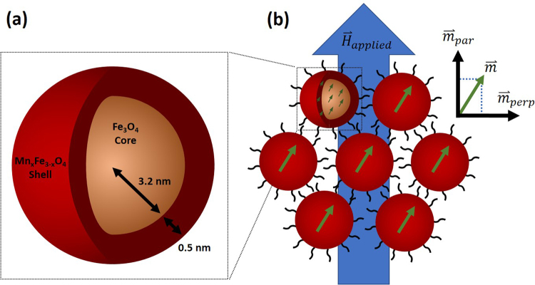
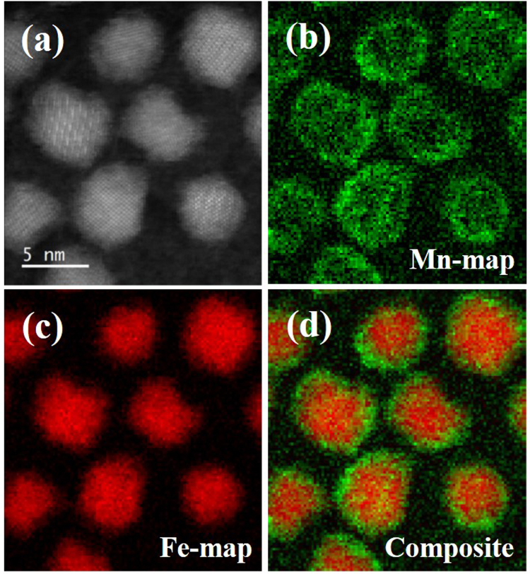
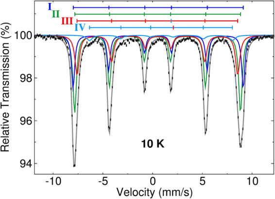
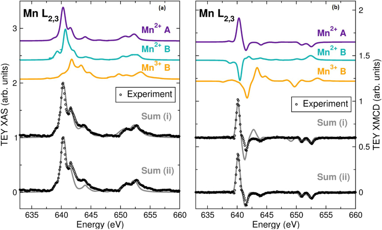
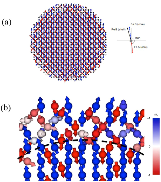
Magnetic nanoparticles (MNPs) have become increasingly important in biomedical applications like magnetic imaging and hyperthermia based cancer treatment. Understanding their magnetic spin configurations is important for optimizing these applications. The measured magnetization of MNPs can be significantly lower than bulk counterparts, often due to canted spins. This has previously been presumed to be a surface effect, where reduced exchange allows spins closest to the nanoparticle surface to deviate locally from collinear structures. We demonstrate that intraparticle effects can induce spin canting throughout a MNP via the Dzyaloshinskii-Moriya interaction (DMI). We study ~7.4 nm diameter, core/shell Fe3O4/MnxFe3-xO4 MNPs with a 0.5 nm Mn-ferrite shell. Mössbauer spectroscopy, x-ray absorption spectroscopy and x-ray magnetic circular dichroism are used to determine chemical structure of core and shell. Polarized small angle neutron scattering shows parallel and perpendicular magnetic correlations, suggesting multiparticle coherent spin canting in an applied field. Atomistic simulations reveal the underlying mechanism of the observed spin canting. These show that strong DMI can lead to magnetic frustration within the shell and cause canting of the net particle moment. These results illuminate how core/shell nanoparticle systems can be engineered for spin canting across the whole of the particle, rather than solely at the surface.
Conflict of interest statement
The authors declare no competing interests.
Figures


Similar articles
-
Effect of spatial confinement on magnetic hyperthermia via dipolar interactions in Fe₃O₄ nanoparticles for biomedical applications.Mater Sci Eng C Mater Biol Appl. 2014 Sep;42:52-63. doi: 10.1016/j.msec.2014.04.064. Epub 2014 May 13. Mater Sci Eng C Mater Biol Appl. 2014. PMID: 25063092
-
Understanding Magnetization Dynamics of a Magnetic Nanoparticle with a Disordered Shell Using Micromagnetic Simulations.Nanomaterials (Basel). 2020 Jun 11;10(6):1149. doi: 10.3390/nano10061149. Nanomaterials (Basel). 2020. PMID: 32545385 Free PMC article.
-
Spin-up conversion, exchange-interactions, and tailored magnetic properties in core-shell La2NiMnO6of small crystallites.Nanotechnology. 2021 Aug 2;32(43). doi: 10.1088/1361-6528/ac13eb. Nanotechnology. 2021. PMID: 34256367
-
Nanoscaling laws of magnetic nanoparticles and their applicabilities in biomedical sciences.Acc Chem Res. 2008 Feb;41(2):179-89. doi: 10.1021/ar700121f. Acc Chem Res. 2008. PMID: 18281944 Review.
-
The Mössbauer and magnetic properties of ferritin cores.Biochim Biophys Acta. 2010 Aug;1800(8):886-97. doi: 10.1016/j.bbagen.2010.03.018. Epub 2010 Apr 2. Biochim Biophys Acta. 2010. PMID: 20363296 Review.
Cited by
-
Interplay between inter- and intraparticle interactions in bi-magnetic core/shell nanoparticles.Nanoscale Adv. 2021 Oct 4;3(24):6912-6924. doi: 10.1039/d1na00312g. eCollection 2021 Dec 7. Nanoscale Adv. 2021. PMID: 36132365 Free PMC article.
-
Uniaxial polarization analysis of bulk ferromagnets: theory and first experimental results.J Appl Crystallogr. 2022 May 28;55(Pt 3):569-585. doi: 10.1107/S1600576722003508. eCollection 2022 Jun 1. J Appl Crystallogr. 2022. PMID: 35719309 Free PMC article.
-
Magnetic correlations of iron oxide nanoparticles as probed by polarized SANS in stretched magnetic nanoparticle-elastomer composites.Appl Phys Lett. 2022;120(5):10.1063/5.0081922. doi: 10.1063/5.0081922. Appl Phys Lett. 2022. PMID: 36620127 Free PMC article.
-
Unraveling the Mn2+ substitution effect on the anisotropy control and magnetic hyperthermia of MnxFe3-xO4 nanoparticles.Nanoscale Horiz. 2025 Aug 4. doi: 10.1039/d5nh00254k. Online ahead of print. Nanoscale Horiz. 2025. PMID: 40755348 Free PMC article.
-
Improvements in the Organic-Phase Hydrothermal Synthesis of Monodisperse M x Fe3-x O4 (M = Fe, Mg, Zn) Spinel Nanoferrites for Magnetic Fluid Hyperthermia Application.ACS Omega. 2020 Jul 17;5(29):18091-18104. doi: 10.1021/acsomega.0c01641. eCollection 2020 Jul 28. ACS Omega. 2020. PMID: 32743183 Free PMC article.
References
Publication types
LinkOut - more resources
Full Text Sources
Other Literature Sources
Molecular Biology Databases
