. 2018 Mar;232(3):299-309.
doi: 10.1177/0954411918754924. Epub 2018 Feb 23.

Correction of radiographic measurements of acetabular cup wear for variations in pelvis orientation

Affiliations

Correction of radiographic measurements of acetabular cup wear for variations in pelvis orientation

Brian Derbyshire. Proc Inst Mech Eng H. 2018 Mar.

Abstract

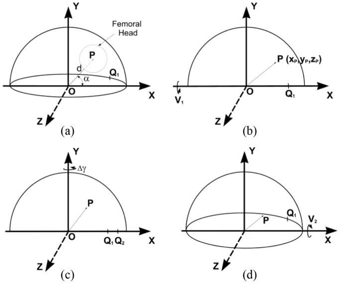
Radiographic measurement of two-dimensional acetabular cup wear is usually carried out on a series of follow-up radiographs of the patient's pelvis. Since the orientation of the pelvis might not be consistent at every X-ray examination, the resulting change in view of the wear plane introduces error into the linear wear measurement. This effect is amplified on some designs of cup in which the centre of the socket is several millimetres below the centre of the cup or circular wire marker. This study describes the formulation of a mathematical method to correct radiographic wear measurements for changes in pelvis orientation. A mathematical simulation of changes in cup orientation and wear vectors caused by pelvic tilt was used to confirm that the formulae corrected the wear exactly if the radiographic plane of the reference radiograph was parallel to the true plane of wear. An error analysis showed that even when the true wear plane was not parallel to the reference radiographic plane, the formulae could still provide a useful correction. A published correction formula was found to be ineffective.

Keywords: Hip prosthesis; acetabular cup wear; pelvic orientation; pelvic tilt; radiographic measurement; total hip replacement; wear correction; wear measurement.


Conflict of interest statement

Declaration of conflicting interests: The author(s) declared no potential conflicts of interest with respect to the research, authorship, and/or publication of this article.

Figures

Figure 1.
Figure 1.
Diagram of the inferior aspect of a pelvis as viewed on an AP radiograph showing the proximal portion of a left total hip replacement. An offset, cemented cup is shown in which the base is extended so that the socket centre is infero-lateral to the cup centre.
Figure 2.
Figure 2.
Following a backwards pelvic tilt (dashed lines), the orientation (version, inclination and polar rotation) of the cup changes together with the 2D position of the femoral head relative to the cup. Rotation of the cup about the polar axis is determined from the change in position of a chosen landmark relative to the lateral end of the cup opening. The changes have been exaggerated for clarity.
Figure 3.
Figure 3.
The effect of a change in cup orientation on a measured wear displacement vector, as viewed on an AP radiograph. The initial cup anteversion is V1 and its inclination I has been set to zero for convenience. (a) OP, a displacement vector between the measured centres of the cup and femoral head, initially has a magnitude d and an angle α to the inclination axis OX. The wear plane is parallel to the XY plane. Q1 is a chosen rotation landmark (here on the anterior rim of the hemispherical cup). (b) The cup has been rotated by V1 about the X-axis to bring the polar axis of the cup in line with the Y-axis. Point P moves to xp, yp, zp. (c) The effect on OP of rotation, Δγ, about the polar axis OY. Q1 moves to Q2. (d) The effect on OP of rotation (from the position in (b)) about the OX axis. The measured anteversion is now V2.
Figure 4.
Figure 4.
(a) Diagram representing an AP radiographic view of a left cup of unit radius in a global, right-hand axis system, XYZ. The cup inclination is set at an angle I1 to the X-axis – which is parallel to a line tangential to the ischial tuberosities (Figure 1). Version is initially zero. OP is a unit displacement vector in the direction of the polar axis of the cup. (b) The cup is anteverted to V1 causing point P to move out-of-plane to P1. Point Q1 is a designated rotation landmark (c) Forwards pelvic tilt φ applied about the X-axis causes a reduction in anteversion from V1 to V2, a reduction in inclination from I1 to I2, a rotation of Q1 to position Q2, and a change of the 2D view of OP1 to OP2. (d) This shows the circular view (from below) of the cup base in (c) after rotating the cup about the inclination axis, Ox′, by π/2 – V2. The line OQ1 has rotated to OQ2 in an anticlockwise direction through an angle ΔR.
Figure 5.
Figure 5.
Geometrical representation of the opening of an offset cup in which the centre of the socket is below the wire marker/shell centre. The displacement vectors dref and df-up between the centre ‘O’ of the wire marker/shell and the centre of the femoral head (C1, C2, respectively) are measured on the reference and follow-up radiographs. Here, dref and df-up are in the radiographic, wear plane. The resulting wear vector ‘w’ is at angle β to the cup opening axis. For convenience, the inclination of the cup has been set at zero.
Figure 6.
Figure 6.
Chart showing the variation of corrected and uncorrected (dashed lines) wear penetration error with true wear direction (β) for a true penetration range of 0.2–1.0 mm (in arrow directions). Settings: reference tilt +10°, follow-up tilt –10°, inclination 30°, true anteversion –20°. Generally, the shape and intersections of the curves varied for different settings. Here, the corrected penetration error was less than about 50° and at mid-range penetrations.
Figure 7.
Figure 7.
(a) The rotation point landmark is chosen to be at the edge of screw hole in the anterior surface of the shell image. (b) Circular view (from above the cup dome) of the cup section containing the rotation point landmark.

Similar articles

Cited by

References

    1. Green TR, Fisher J, Mathews JB, et al. Effect of size and dose on bone resorption of macrophages by in vitro clinically relevant ultra high molecular weight polyethylene particles. J Biomed Mater Res 2000; 53: 490–497. - PubMed
    1. Kobayashi A, Freeman MAR, Bonfield W, et al. Number of polyethylene particles and osteolysis in total joint replacements. J Bone Joint Surg Br 1997; 79-B: 844–848. - PubMed
    1. Orishimo KF, Claus AM, Sychterz CJ, et al. Relationship between polyethylene wear and osteolysis in hips with a second-generation porous-coated cementless cup after seven years of follow-up. J Bone Joint Surg Am 2003; 85: 1095–1099. - PubMed
    1. Dumbleton JH, Manley MT, Edidin AA. A literature review of the association between wear rate and osteolysis in total hip arthroplasty. J Arthroplasty 2002; 17: 649–661. - PubMed
    1. Rajpura A, Kendoff D, Board TN. The current state of bearing surfaces in total hip replacement. Bone Joint J 2014; 96-B: 147–156. - PubMed

LinkOut - more resources