. 2018 Feb 23;9(1):812.
doi: 10.1038/s41467-018-03155-6.

MEMS-tunable dielectric metasurface lens

Affiliations

MEMS-tunable dielectric metasurface lens

Ehsan Arbabi et al. Nat Commun. .

Abstract

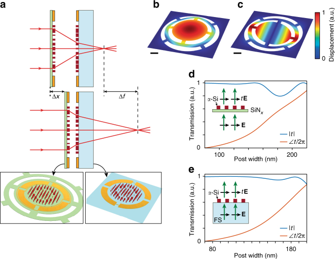
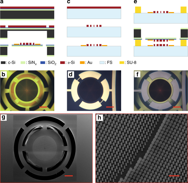
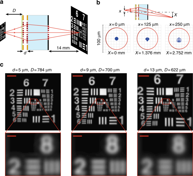
Varifocal lenses, conventionally implemented by changing the axial distance between multiple optical elements, have a wide range of applications in imaging and optical beam scanning. The use of conventional bulky refractive elements makes these varifocal lenses large, slow, and limits their tunability. Metasurfaces, a new category of lithographically defined diffractive devices, enable thin and lightweight optical elements with precisely engineered phase profiles. Here we demonstrate tunable metasurface doublets, based on microelectromechanical systems (MEMS), with more than 60 diopters (about 4%) change in the optical power upon a 1-μm movement of one metasurface, and a scanning frequency that can potentially reach a few kHz. They can also be integrated with a third metasurface to make compact microscopes (~1 mm thick) with a large corrected field of view (~500 μm or 40 degrees) and fast axial scanning for 3D imaging. This paves the way towards MEMS-integrated metasurfaces as a platform for tunable and reconfigurable optics.


Conflict of interest statement

The authors declare no competing financial interests.

Figures

Fig. 1
Fig. 1
Schematic illustration of the tunable doublet and design graphs. a Schematic illustration of the proposed tunable lens, comprised of a stationary lens on a substrate, and a moving lens on a membrane. With the correct design, a small change in the distance between the two lenses (Δx ~ 1 μm) results in a large change in the focal distance (Δf ~ 35 μm). (Insets: schematics of the moving and stationary lenses showing the electrostatic actuation contacts.) b The first and c second mechanical resonances of the membrane at frequencies of ~2.6 and ~5.6 kHz, respectively. The scale bars are 100 μm. d Simulated transmission amplitude and phase for a uniform array of α-Si nano-posts on a ~213-nm-thick SiNx membrane versus the nano-post width. The nano-posts are 530 nm tall and are placed on the vertices of a square lattice with a lattice constant of 320 nm. e Simulated transmission amplitude and phase for a uniform array of α-Si nano-posts on a glass substrate versus the nano-post width. The nano-posts are 615 nm tall and are placed on the vertices of a square lattice with a lattice constant of 320 nm. FS: Fused silica
Fig. 2
Fig. 2
Fabrication process summary. a Simplified fabrication process of a lens on a membrane: a SiO2 spacer layer and an α-Si layer are deposited on a Si substrate with a pre-deposited SiNx layer. The backside of the substrate is partially etched, and alignment marks are etched into the α-Si layer. The lens is patterned and etched into the α-Si layer, and gold contacts are evaporated on the membrane. The remaining substrate thickness is etched and the membrane is released. c-Si: crystalline silicon; FS: fused silica. b An optical microscope image of a fabricated lens on a membrane. c Simplified fabrication process of the lens on the glass substrate: an α-Si layer is deposited on a glass substrate and patterned to form the lens. Gold contacts are evaporated and patterned to from the contacts. d An optical microscope image of the fabricated lens on the glass substrate. e Schematics of the bonding process: an SU-8 spacer layer is patterned on the glass substrate, the two chips are aligned and bonded. f A microscope image of the final device. g Scanning electron micrograph of the lens on the membrane, and h nano-posts that form the lens. Scale bars are 100 μm in b, d, f, and g, and 1 μm in h
Fig. 3
Fig. 3
Focusing measurement results of the tunable doublet. a Simulated EFL versus the distance between lenses, along with measured EFL values for 8 devices under different applied voltages. Different devices have different initial lens separations, resulting in different focal distances under no applied voltage. b Measured front focal length versus the applied DC voltage for device 2 of panel a. The separation values between the moving and stationary lenses are also plotted. c Intensity distributions in the focal plane of the doublet lens at different actuation voltages. The scale bars are 2 μm. d Measured Airy radii (normalized to their corresponding diffraction-limited values), r¯A, and measured absolute focusing efficiency of the tunable doublet. e Measured frequency response of the system, along with second order transfer functions with two values of the damping factor (b) equal to 20mk and mk
Fig. 4
Fig. 4
Imaging with the tunable doublet. a Schematic illustration of the imaging setup using a regular glass lens and the tunable doublet. The image formed by the doublet is magnified and re-imaged using a custom-built microscope with a ×55 magnification onto an image sensor. b Imaging results, showing the tuning of the imaging distance of the doublet and glass lens combination with applied voltage. By applying 85 V across the device, the imaging distance p increases from 4 to 15 mm. The scale bars are 10 μm
Fig. 5
Fig. 5
Tunable focus metasurface microscope. a Schematic illustration of a metasurface triplet operating as a compact electrically tunable microscope. The metasurfaces have diameters of 540, 560, and 400 μm from the left to the right, respectively, and the glass substrate is 1 mm thick. Moving the membrane by about 8 μm moves the object plane more than 160 μm. b Ray optics simulation of spot diagrams of the microscope for the case of d = 9 μm. The inset shows a schematic of the triplet, the locations of the point source in the object plane and the image plane. The phase profiles of the metasurfaces are designed to keep the focus almost diffraction limited for a 500-μm-diameter field of view when d is changed from 5 to 13 μm. The system has a magnification close to 11 and a numerical aperture of 0.16 when d = 9 μm. c Image simulation results using the triplet for different values of d and D. The scale bars are 50 μm in the zoomed-out images, and 5 μm in the zoomed-in areas

References

    1. Jeong KH, Liu GL, Chronis N, Lee LP. Tunable microdoublet lens array. Opt. Express. 2004;12:2494–2500. doi: 10.1364/OPEX.12.002494. - DOI - PubMed
    1. Lee SW, Lee SS. Focal tunable liquid lens integrated with an electromagnetic actuator. Appl. Phys. Lett. 2007;90:121129. doi: 10.1063/1.2716213. - DOI
    1. Sato S. Liquid-crystal lens-cells with variable focal length. Jpn. J. Appl. Phys. 1979;18:1679–1684. doi: 10.1143/JJAP.18.1679. - DOI
    1. Ren H, Fan YH, Gauza S, Wu ST. Tunable-focus flat liquid crystal spherical lens. Appl. Phys. Lett. 2004;84:4789–4791. doi: 10.1063/1.1760226. - DOI
    1. Pishnyak O, Sato S, Lavrentovich OD. Electrically tunable lens based on a dual-frequency nematic liquid crystal. Appl. Opt. 2006;45:4576–4582. doi: 10.1364/AO.45.004576. - DOI - PubMed

Publication types