

Reversible conduction block in peripheral nerve using electrical waveforms
- PMID: 29480897
- PMCID: PMC5811084
- DOI: 10.2217/bem-2017-0004
Reversible conduction block in peripheral nerve using electrical waveforms
Abstract
Introduction: Electrical nerve block uses electrical waveforms to block action potential propagation.
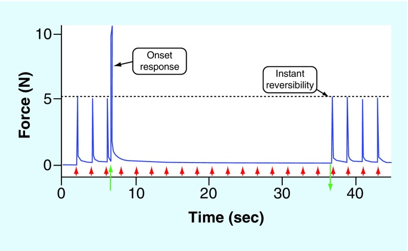
Materials & methods: Two key features that distinguish electrical nerve block from other nonelectrical means of nerve block: block occurs instantly, typically within 1 s; and block is fully and rapidly reversible (within seconds).
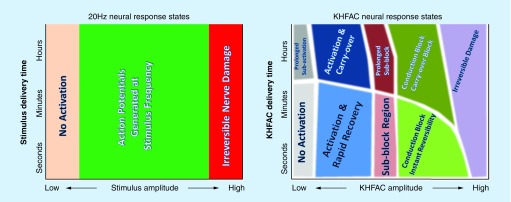
Results: Approaches for achieving electrical nerve block are reviewed, including kilohertz frequency alternating current and charge-balanced polarizing current. We conclude with a discussion of the future directions of electrical nerve block.
Conclusion: Electrical nerve block is an emerging technique that has many significant advantages over other methods of nerve block. This field is still in its infancy, but a significant expansion in the clinical application of this technique is expected in the coming years.
Keywords: action potential; direct current; electrical nerve block; kilohertz frequency; neuromodulation; neuroprosthesis.
Conflict of interest statement
Financial & competing interests disclosure This work was supported by NIH NINDS R01-NS-074149, NIBIB R01-EB-002091 and the Case Coulter Translation & Innovation Partnership. K Kilgore and N Bhadra have equity ownership in Neuros Medical, Inc. The authors have no other relevant affiliations or financial involvement with any organization or entity with a financial interest in or financial conflict with the subject matter or materials discussed in the manuscript apart from those disclosed. No writing assistance was utilized in the production of this manuscript.
Figures
Similar articles
-
Effects of waveform shape and electrode material on KiloHertz frequency alternating current block of mammalian peripheral nerve.Bioelectron Med. 2022 Jul 27;8(1):11. doi: 10.1186/s42234-022-00093-z. Bioelectron Med. 2022. PMID: 35883133 Free PMC article.
-
Reversible nerve conduction block using kilohertz frequency alternating current.Neuromodulation. 2014 Apr;17(3):242-54; discussion 254-5. doi: 10.1111/ner.12100. Epub 2013 Aug 7. Neuromodulation. 2014. PMID: 23924075 Free PMC article. Review.
-
Combining direct current and kilohertz frequency alternating current to mitigate onset activity during electrical nerve block.J Neural Eng. 2021 Mar 22;18(4):10.1088/1741-2552/abebed. doi: 10.1088/1741-2552/abebed. J Neural Eng. 2021. PMID: 33662942 Free PMC article.
-
Kilohertz Electrical Stimulation Nerve Conduction Block: Effects of Electrode Material.IEEE Trans Neural Syst Rehabil Eng. 2018 Jan;26(1):11-17. doi: 10.1109/TNSRE.2017.2737954. Epub 2017 Aug 10. IEEE Trans Neural Syst Rehabil Eng. 2018. PMID: 28809704
-
Measurement of block thresholds in kiloHertz frequency alternating current peripheral nerve block.J Neurosci Methods. 2019 Mar 1;315:48-54. doi: 10.1016/j.jneumeth.2019.01.002. Epub 2019 Jan 11. J Neurosci Methods. 2019. PMID: 30641091 Free PMC article. Review.
Cited by
-
Kilohertz waveforms optimized to produce closed-state Na+ channel inactivation eliminate onset response in nerve conduction block.PLoS Comput Biol. 2020 Jun 15;16(6):e1007766. doi: 10.1371/journal.pcbi.1007766. eCollection 2020 Jun. PLoS Comput Biol. 2020. PMID: 32542050 Free PMC article.
-
HFAC Dose Repetition and Accumulation Leads to Progressively Longer Block Carryover Effect in Rat Sciatic Nerve.Front Neurosci. 2022 May 27;16:852166. doi: 10.3389/fnins.2022.852166. eCollection 2022. Front Neurosci. 2022. PMID: 35712453 Free PMC article.
-
Closed-loop electrical block of vagus nerve scales from rodent to porcine cardiac models.J Neural Eng. 2025 May 27;22(3):036022. doi: 10.1088/1741-2552/add8be. J Neural Eng. 2025. PMID: 40367967 Free PMC article.
-
Transcutaneous electrical nerve inhibition using medium frequency alternating current.Sci Rep. 2022 Sep 1;12(1):14911. doi: 10.1038/s41598-022-18974-3. Sci Rep. 2022. PMID: 36050354 Free PMC article. Clinical Trial.
-
Measurement of Peripheral Nerve Magnetostimulation Thresholds of a Head Solenoid Coil Between 200 Hz and 88.1 kHz.IEEE J Transl Eng Health Med. 2025 May 15;13:275-285. doi: 10.1109/JTEHM.2025.3570611. eCollection 2025. IEEE J Transl Eng Health Med. 2025. PMID: 40740830 Free PMC article.
References
-
- Hambrecht FT. Functional electrical-stimulation – an overview. Pace-Pacing and Clinical Electrophysiol. 1989;12(5):840–843. - PubMed
-
- Linderoth B, Foreman RD. Physiology of spinal cord stimulation: review and update. Neuromodulation. 1999;2(3):150–164. - PubMed
-
- Bhadra N, Kilgore KL. High-frequency electrical conduction block of mammalian peripheral motor nerve. Muscle Nerve. 2005;32(6):782–790. - PubMed
-
- Foldes EL, Ackermann D, Bhadra N, Kilgore KL. Counted cycles method to quantify the onset response in high-frequency peripheral nerve block. Conf. Proc. IEEE Eng. Med. Biol. Soc. 2009;2009:614–617. - PubMed
Publication types
Grants and funding
LinkOut - more resources
Full Text Sources
Other Literature Sources
Medical