. 2018 Feb 26;8(1):3605.
doi: 10.1038/s41598-018-22019-z.

Light Emission from Plasmonic Nanostructures Enhanced with Fluorescent Nanodiamonds

Affiliations

Light Emission from Plasmonic Nanostructures Enhanced with Fluorescent Nanodiamonds

Jingyi Zhao et al. Sci Rep. .

Abstract

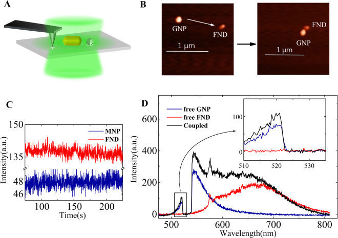
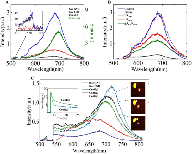
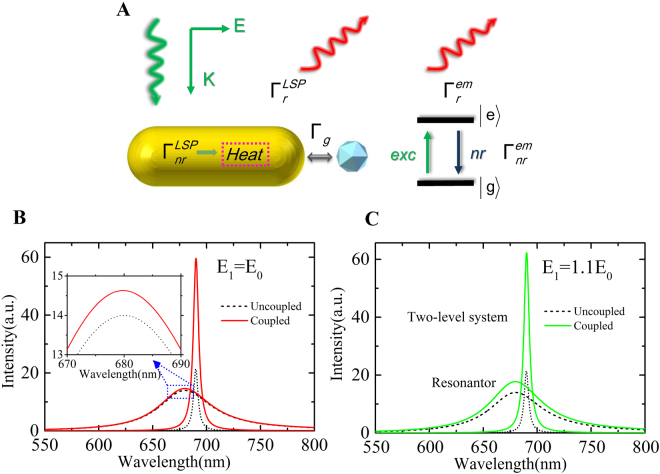
In the surface-enhanced fluorescence (SEF) process, it is well known that the plasmonic nanostructure can enhance the light emission of fluorescent emitters. With the help of atomic force microscopy, a hybrid system consisting of a fluorescent nanodiamond and a gold nanoparticle was assembled step-by-step for in situ optical measurements. We demonstrate that fluorescent emitters can also enhance the light emission from gold nanoparticles which is judged through the intrinsic anti-Stokes emission owing to the nanostructures. The light emission intensity, spectral shape, and lifetime of the hybrid system were dependent on the coupling configuration. The interaction between gold nanoparticles and fluorescent emitter was modelled based on the concept of a quantised optical cavity by considering the nanodiamond and the nanoparticle as a two-level energy system and a nanoresonator, respectively. The theoretical calculations reveal that the dielectric antenna effect can enhance the local field felt by the nanoparticle, which contributes more to the light emission enhancement of the nanoparticles rather than the plasmonic coupling effect. The findings reveal that the SEF is a mutually enhancing process. This suggests the hybrid system should be considered as an entity to analyse and optimise surface-enhanced spectroscopy.


Conflict of interest statement

The authors declare no competing interests.

Figures

Figure 1
Figure 1
Scheme of nano-manipulation and representative in situ optical measurements. (A) Scheme of the AFM manipulation method, (B) representative AFM images during the assembly process. (C) Time trace of the PL intensity of a gold nanoparticle and a nanodiamond. (D) The PL spectra of a free GNP (dark blue) and a free FND (red) before coupling and the SEF spectrum (black) after coupling. The inset shows a magnification of the area showing the anti-Stokes component.
Figure 2
Figure 2
A complete analysis of the three components of the SEF spectrum and coupling-configuration-dependent SEF spectra. (A) The PL spectra of a free GNR (black) and a free FND (red) before coupling, the SEF spectrum (blue) and scattering spectrum (green) after the coupling of GNR and FND. (B) Fitting spectra for I1SGNR0, I2SFND0, and gcSˆSCASˆFND0. (C) Configuration-dependent SEF spectra of the hybrid. The spectra of a free GNR (blue) and a free FND (red) before coupling, and three SEF spectra of three different configurations, as indicated by the AFM and schematic images. The inset shows the lifetime curves of the config. 1 and config. 3 configurations for comparison.
Figure 3
Figure 3
Scheme of the interaction between a FND and a GNR and theoretical analysis of the influence of the dipole coupling effect and local field of the dielectric particle. Simulated spectra of a resonator (black dash) and an atom (black dot) for g = 0, and corresponding spectra (solid curves) after coupling for g = 10 meV (A) the applied electromagnetic field E induces polarisations that causes dipole–dipole coupling Γg between the resonator and the atom and light emission ΓrLSP from the GNR including both elastic and inelastic radiation processes. (B) Local field felt by the GNR for E1 = E0, i.e., without the dielectric nanoantenna effect (C) for E1 = 1.1E0 owing to the induced field of the polarised FND. The inset in (B) presents an enlarged view of the enhanced emission of the resonator.
Figure 4
Figure 4
Field distributions (X–Z plane) of (A) a GNR with a DNP, (B) only a DNP, and (C) only a GNR. (B) The DNP with a diameter of 40 nm and refractive index of 2.3 in the FDTD calculations; the averaged field felt by the GNR (white dot range) is higher than the external excitation filed. (C) Near-field EM distribution around a GNR (60 nm×120 nm) at a wavelength of 532 nm. The white dot range shows the region of the DNP. (D) Ratio of emission flux from a GNR toward a glass substrate to total flux with (black dot) or without (green solid) the DNP as a function of wavelength. The inset in (D) shows representative emission patterns toward a glass substrate or air as indicated at a wavelength of 680 nm.

References

    1. Moskovits M. Surface-enhanced spectroscopy. Rev. Mod. Phys. 1985;57:783. doi: 10.1103/RevModPhys.57.783. - DOI
    1. Fort E, Grésillon S. Surface enhanced fluorescence. J. Phys. D: Appl. Phys. 2008;41:013001. doi: 10.1088/0022-3727/41/1/013001. - DOI
    1. Acuna GP, et al. Fluorescence enhancement at docking sites of DNA-Directed self-assembled nanoantennas. Science. 2012;338:506. doi: 10.1126/science.1228638. - DOI - PubMed
    1. Pelton M. Modified spontaneous emission in nanophotonic structures. Nat. Photon. 2015;9:427. doi: 10.1038/nphoton.2015.103. - DOI
    1. Anger P, Bharadwaj P, Novotny L. Enhancement and quenching of single-molecule fluorescence. Phys. Rev. Lett. 2006;96:113002. doi: 10.1103/PhysRevLett.96.113002. - DOI - PubMed